A null type recorder is a type of strip chart recorder. These recorders are based on the principle of null condition or self balancing principle.
This type of recorder consists of a measuring circuit which is at balanced condition. The circuit becomes imbalanced when an input signal is applied to it. Due to the imbalance created by the input signal an error signal is generated. The error signal is the difference between the input signal and a reference signal. Hence, the measuring circuit used in a null type recorder is a comparison circuit. The error signal is used to operate an instrument which balances the circuit. The balancing instrument is usually a type of moving mechanism which moves the wiper in such a direction which reduces the error and balances the circuit. The balancing instrument moves by an amount proportional to the magnitude of the error. The recording peu is connected to the balancing instrument in such a way that the signal gets recorded during the balance of the circuit i.e., the recording pen moves in synchronism with the wiper. The recording process comes to an end when the null condition is attained (i.e. when error = 0). The most commonly used null type recorders are of three types. They are,
- Potentiometric recorder.
- LVDT recorder.
- Bridge recorder.
Potentiometric Recorder
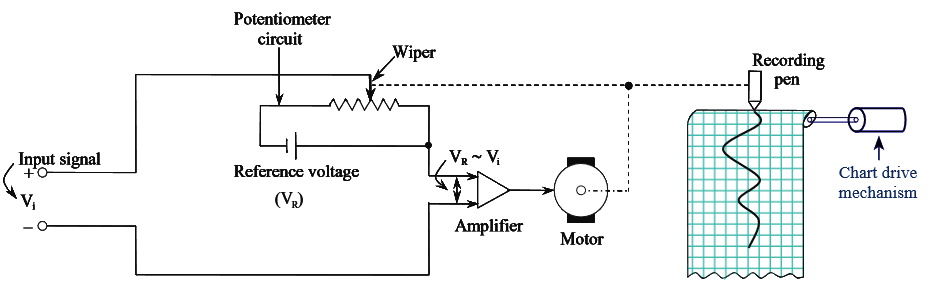
Figure 1: Potentiometric Recorder.
In potentiometric recorder, the principle of recording (i.e., null type condition or self-balancing) is implemented by comparing the input voltage to be recorded with the voltage (reference voltage) of a potentiometer. The comparison (difference) between the input voltage and reference voltage results in an error voltage. The error voltage is then amplified by an op-amp and applied as an input to the D.C motor.
The wiper of the potentiometer is mechanically connected to the armature of the D.C motor therefore the rotation of the armature causes the movement of wiper in the direction which decreases the amount of error. When the error becomes zero there will be no supply to the D.C motor due to which the armature of the motor stops and consequently the wiper also comes to rest and thus a null condition is achieved. The figure below shows the potentiometric recorder.
As the recording pen is connected to the wiper, the recording pen moves over the rolling graph paper by an amount and direction same as that of the wiper. In potentiometric recorders, the chart (graph paper) is moved by chart drive mechanism which is synchronized to the power line frequency. Thus, in the process of balancing the input signal against the potentiometer voltage, the input signal gets recorded.