The X-Y recorders are the devices that record the variation in one dependent variable with respect to an independent variable. The graphical record of one variable against another variable is known as an X-Y record.
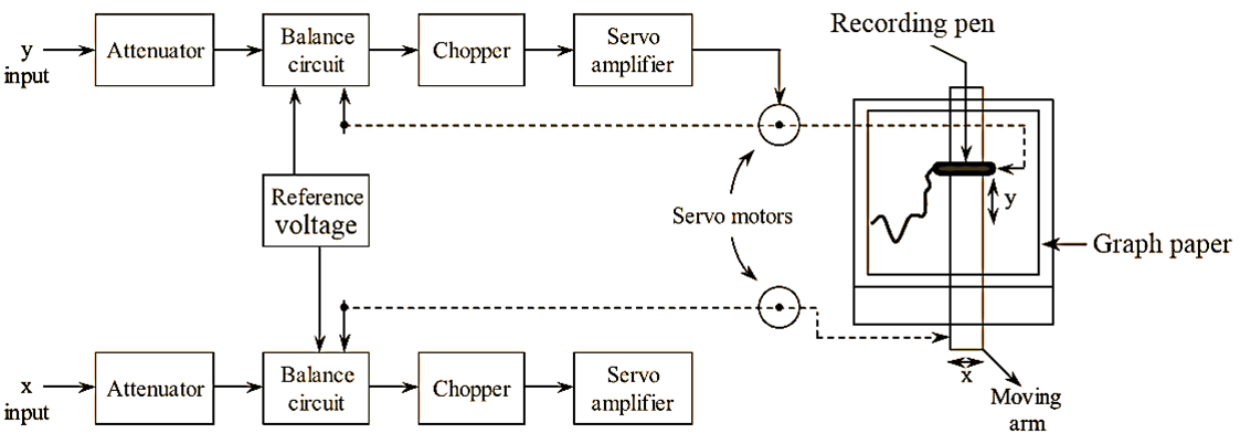
Figure 1: XY Recorder.
In X-Y recording, the graph paper is held stationary, while the recording head is allowed to deflect in X-direction as well as in Y-direction simultaneously in order to obtain X- Y record on the graph paper. The recording head is an assembly of a sliding pen and a moving arm. The recording pen is mounted on the moving arm in such a way that it is able to slide over the moving ann. The moving arm moves in horizontal (X) direction and the sliding pen moves in vertical (Y) direction. The simultaneous movement of the moving arm and recording pen results in the trace of an X- Y record on the graph paper.
For both X and Y deflections, the principle of null or balance condition is employed. Hence, the two input voltages representing the two variables are compared with the reference voltages through a balance circuit as shown in the figure. The null condition is obtained with the help of a servo feedback system (i.e., a system consisting of a chopper, servo-amplifier and a servo motor). Hence, an X-Y recorder consists of two servo systems, one servo system drives the arm in horizontal direction and another servo system drives the recording pen in vertical direction.
The signals representing the x and y parameters are fed as input to the X-Y recorder respectively. Initially each of the signal gets attenuated to the voltage level in the working range (i.e., 0-5 mV) of X-Y recorder. After attenuation the signal is then fed to the balance circuit where the input signal is compared with the reference voltage. The result of the comparison (i.e., error voltage = difference of input voltage and reference voltage) will be a D.C signal which is then converted into an A.C signal by means of the chopper. This A.C error signal is then amplified by a servo amplifier (in order to operate a servo motor) and applied as input to the servo motor. The servo motor is linked to the wiper of the balance circuit and to the recording head. The motor operates the wiper in a direction which minimizes the error and thus balances the system. The operation of the servo motor by the error voltage causes the movement of the recording head (pen/arm) in the respective X and Y direction until the system gets balanced.
Therefore, whenever there is a variation or change in the value of the quantity being recorded the servo motor gets activated and brings the system to the balance condition and hence records the change in the variable.