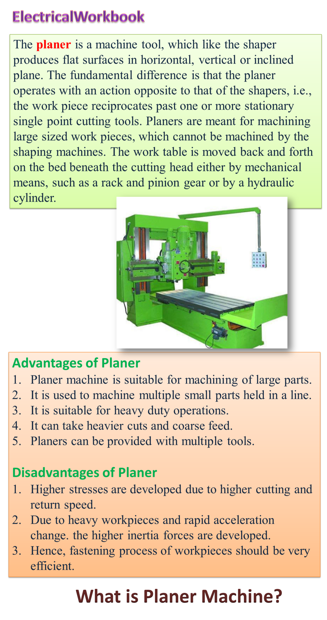
Working Principle of Planer Machine
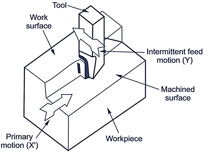
Fig. 1: Principle of operation of a planer.
Planers are rarely used for production work as they are less efficient than other machining processes like milling, grinding etc. In case of planer, the work table slides in the guideways of machine bed. The work table is provided with T-slots for mounting the workpiece (see Figure 1).
The cutting tools are held in tool head and can slide horizontally on cross rail (in a direction perpendicular to the direction of movement of work table). The cutting tool can also be adjusted vertically with the up and down movement of crossrail. Cross rail can slide on vertical guideways of column. Cross rail may move up and down by elevating screws accommodated with in column. Cutting is achieved by movement of work table in guideways (motion X) and feeding the tool at right angle to the movement (Y). Like the shaper, tool post is mounted on the clapper box to avoid interference between the cutting tool and table during idle stroke.
Parts of Planer Machine
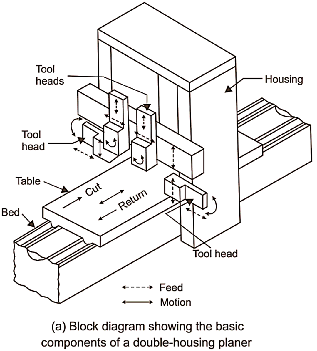
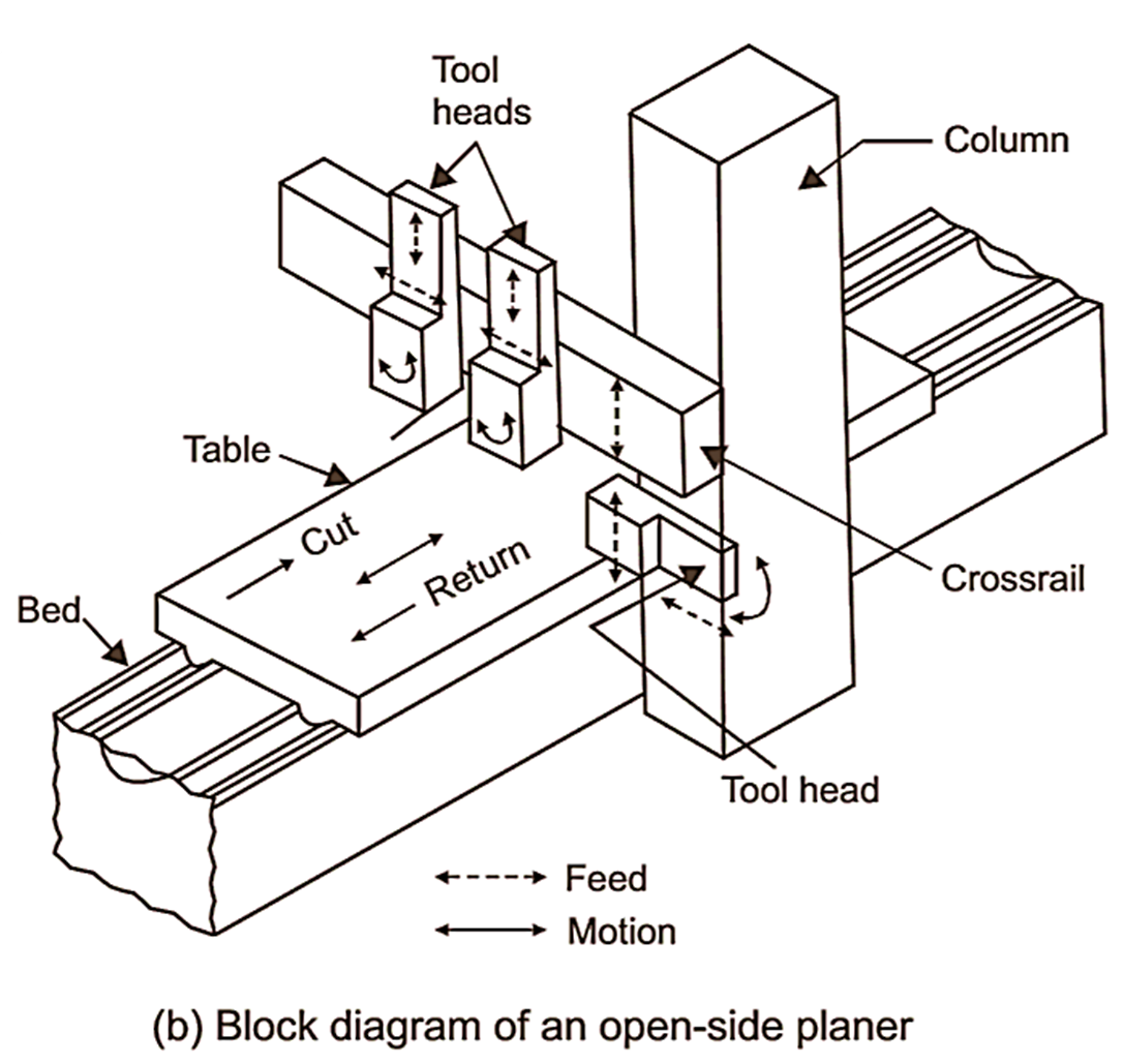
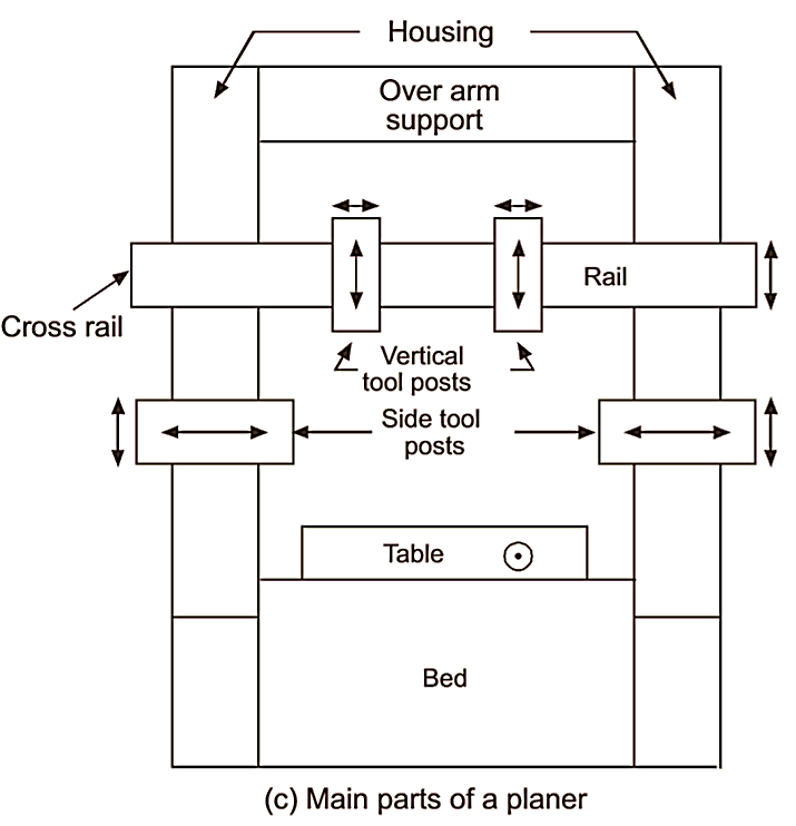
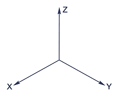
Fig. 2: Planer machine.
Main parts (see Figure 2) of a double housing planer are:
- Bed
- Worktable
- Housing and columns
- Cross rail
- Tool head
- Driving and feed mechanism
Bed:
Planer bed is strong and robust structure made of cast iron. The bed acts as foundation of machine and supports other parts of planer. The length of bed is slightly more than the length of stroke. For movement of work table on bed dovetail, flat or V guideways are provided on the top of the bed. For lubrication of guideways, pressure lubrication is adopted. The hollow space with in the box like structure of bed houses the driving mechanisms of work table.
Work table:
The work table holds and supports the workpiece. It slides on the guideways provided in the bed. The worktable is heavy rectangular shape and is made of cast iron. The top face of cast table is accurately finished to locate the workpiece. The T slots are provided on the table so that workpiece and work holding devices may be bolted upon it. Accurately machined holes are also there on top surface of worktable to support stop pins.
Housing and columns:
The columns are vertical members and are there on both sides of the bed in case of double housing planer and on one side in case of an open side planer. In the front of columns, accurately machined guideways are there along which cross rail may slide up and down. Columns enclose cross rail elevating screw, vertical and cross feed screws for vertical and horizontal movement of tool head. These screws may be operated either by hand or power. The column also encloses counter balancing weight for cross rail.
Cross rail:
Cross rail is heavy box like construction between two columns. The cross rail slides on vertical guideways of column. The movement of cross rail may be controlled by hand or by power operated screws. The purpose of cross rail is to carry tool head and to provide cross feed and vertical movements (up and down) to cutting tool. Up and down (vertical) movement to cutting tool or tool head is provided by means of an elevating screw accommodated with in column. The cross feed screw is used for the cross feed movement of tool head. It is very essential that cross rail must remain parallel to work table during cutting to achieve accurate machined surfaces of workpiece.
Tool head:
The tool head of planer is similar to that of shaper in construction. Important parts of tool head are tool slide, swivel base, clapper box, clapper block, tool post. The clapper box of tool head carries a tool post in which cutting tool is held. The tool post is hinged to tool head for the tool during backward (idle) stroke. The tool head slides in the horizontal guideways of cross rail.
Operations Performed on Planer Machine
Operations performed on planer machine are similar to that of shaper. The only difference is that planers are used for planing large workpieces which can not be accommodated by shaper (see Figure 3). The common operations performed on a planer are:
- Planing flat horizontal surfaces.
- Planing vertical surfaces.
- Planing at an angle.
- Planing slots and grooves.
- Planing curved surfaces.
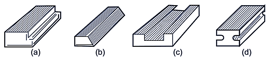
Fig. 3: Various surfaces machined by planer.
Work Holding Devices for Planer Machine
Since heavy cuts (as much as 25 mm) are taken at a speed of 20-30 m/minute on a planer, the workpiece must be properly fastened to the work table, various type of devices used for hold workpieces on planer worktable are:
- Planer vice
- V blocks
- Angle plate
- Paralleiships
- Cramps
- Holding with dogs
- T bolt, nut, washer, wedges and packings etc.
Specifications of Planer Machine
Planers are made in different sizes and are specified by following dimensions:
- Horizontal distance between vertical columns.
- Vertical distance between top surface of table and cross rail, (when the cross rail is at the max. height).
- Maximum length of stroke.
The above three dimensions are principal dimensions and provide the measure of maximum size of the job that can be machined on a particular planer. In addition to these other specifications are:
- Length of bed.
- Length of table.
- Mechanism of driving table (geared or hydraulic)
- Horsepower of motor.
- Number of feeds available.
- Floor space required.
- Net weight of the machine.