The silicon bilateral switch is abbreviated as SBS. Basically, it is a bilateral four layer silicon diode with two electrodes. It is a member of thyristor family. It is available with switching voltage of diode 6 to 10V. It has the rating of about 100 V, 200 mA. It is a bidirectional device.
Construction of Silicon Bilateral Switch
The SBS is made up of two identical SUS devices arranged in antiparallel with two electrodes. The basic structure of a SBS is as shown in Fig. 1 (a).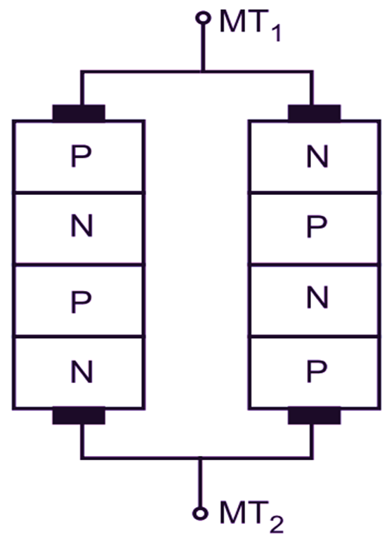
(a) Basic Structure
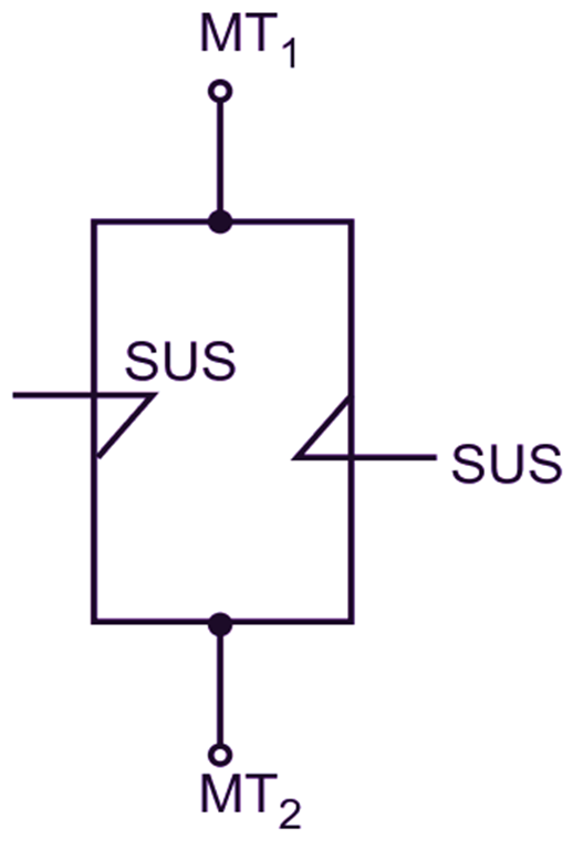
(b) Equivalent structure
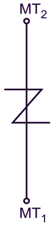
(c) Symbol
Fig. 1: Construction of SBS
It has only two electrodes, namely main terminal MT1 and main terminal MT2. Fig. 1 (b) shows the equivalent structure of SBS. Fig. 1 (c) shows the schematic symbol of SBS.
Principle of Operation of Silicon Bilateral Switch
The operation of SBS is similar to that of a TRIAC with open gate. The equivalent circuit of a SBS is as shown in Fig. 2.
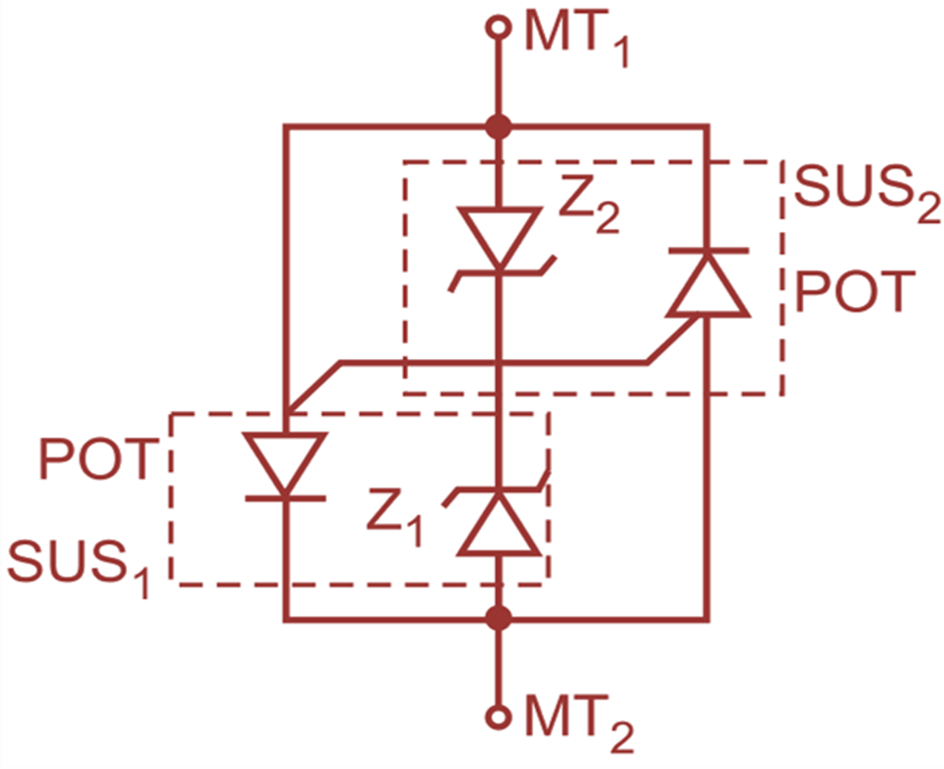
Fig. 2: Operation of SBS
It consists of two identical. i.e. matched characteristics, SUS devices connected in antiparallel. When the terminal MT1 is positive with respect to the terminal MT2 and internally the gate is forward biased but it open, the SUS1 will not conduct till the forward voltage Vt is below the avalanche voltage VZ1. This is the forward blocking (OFF) state of SBS. When the forward voltage Vt exceeds the breakover voltage VZ1 of the internal avalanche diode, i.e. Vt > VZ1, the SUS1 will conduct the current from MT1 to MT2. The SBS is now in forward conduction (ON) state. When the terminal MT1 is negative with respect to the terminal MT2 and the internal gate is open; the SUS2 is forward biased hut it will not conduct till the forward voltage Vt is below the breakover voltage VZ2 of an internal avalanche diode Z2. This is reverse blocking (OFF) state. When the reverse voltage exceeds the breakover voltage VZ2 the SUS2 will conduct the current from MT2 to MT1. The SBS is now in reverse conduction (ON) state. The breakover voltage is about 6 to 10 V. If the applied voltage exceeds the breakover voltage, then SBS turns ON from its OFF state in forward as well as reverse bias conditions. When SBS is ON, the voltage drop across it is about 1.7 V. Thus, SBS conducts in either direction.
V-I Characteristics of Silicon Bilateral Switch
The V-I characteristics of SBS is as shown in Fig. 3. At the breakover (or switching) voltage, SBS conducts the current in forward bias as well as reverse bias conditions and turns ON in either direction. At the breakover voltage, the terminal current increases rapidly but the voltage drops across it. This is observed in forward bias as well as reverse bias conditions.
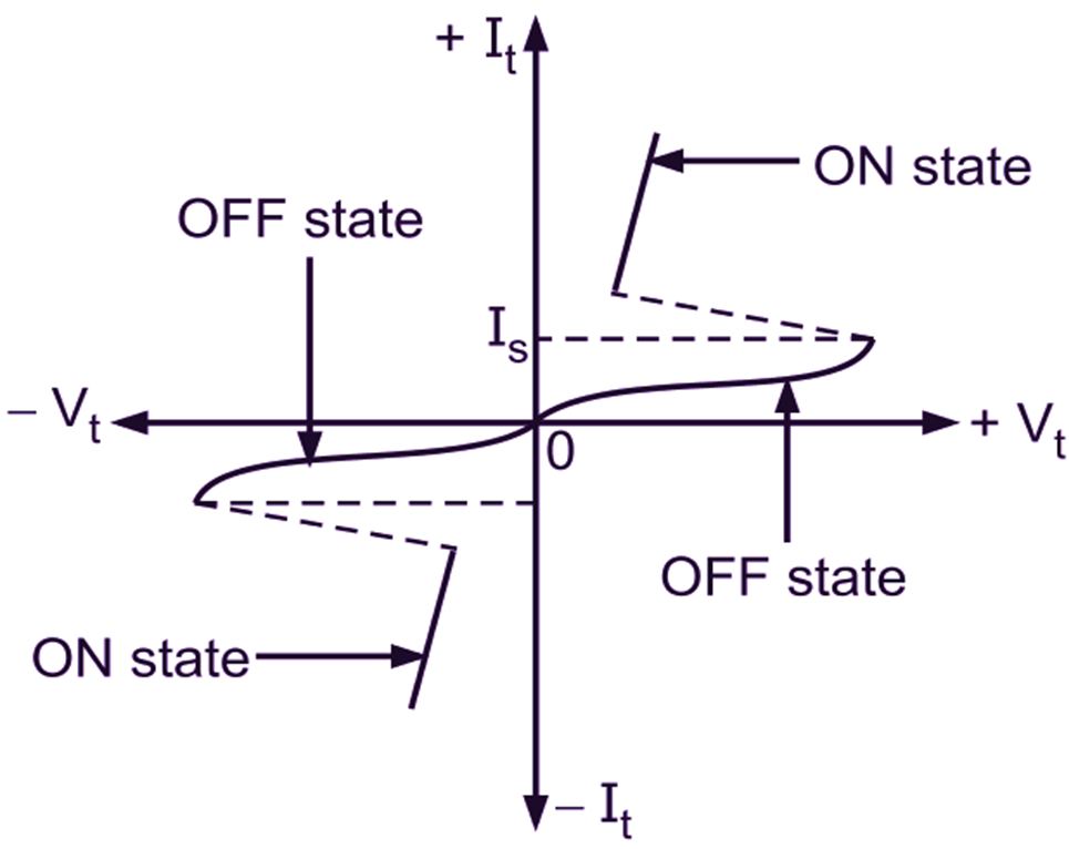
Fig. 3: V-I characteristics of SBS
Applications of Silicon Bilateral Switch
The applications of SBS are as given below:
- It is used for triggering of TRIACs.
- It is used for AC phase control by TRIACs.