In this topic, you study Single Phase Generator – Working, Construction, & Diagram.
The working of an elementary 2-pole single-phase alternator shown in Fig. 1.
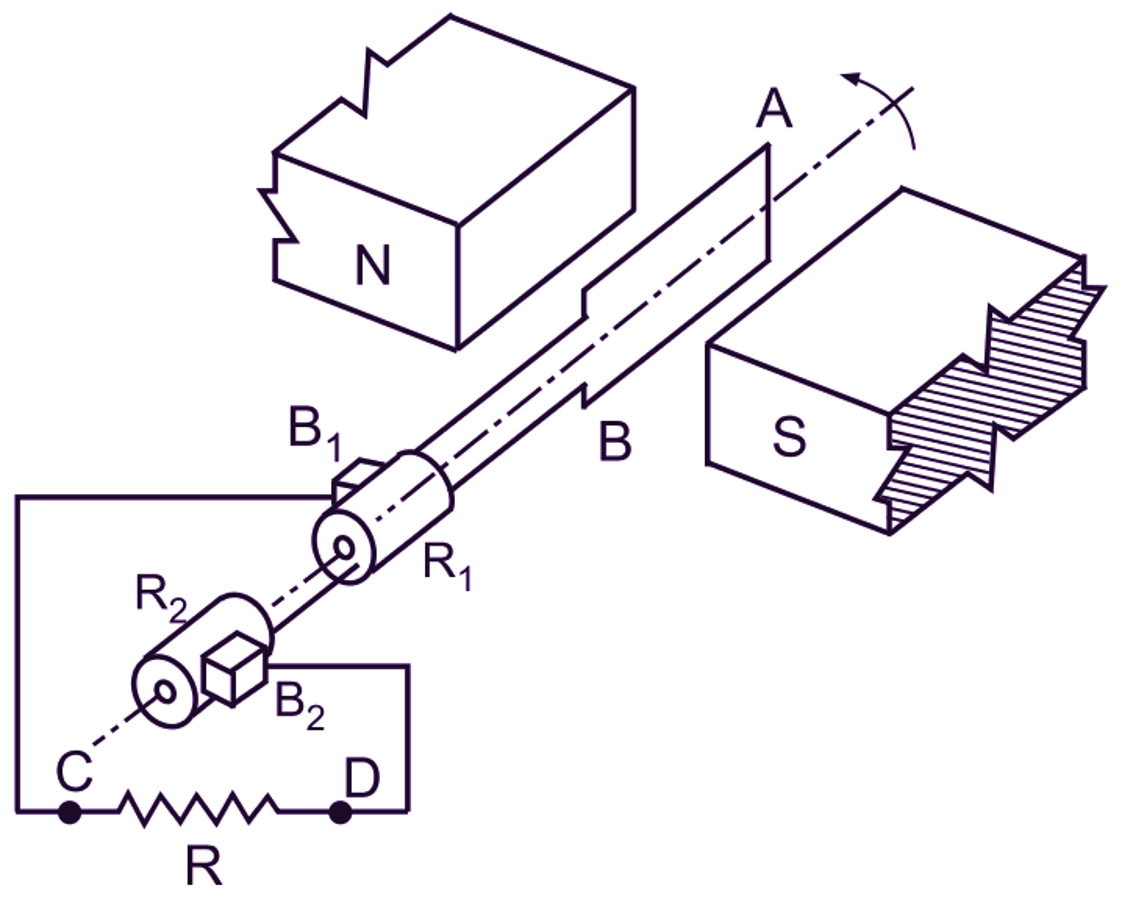
Fig. 1: An elementary single-phase alternator with two poles
Construction of Single Phase Generator
It consists of a single turn rectangular coil (AB) made up of some conducting material like copper or aluminium. The coil is so placed that it can be rotated about its own axis at a constant speed in a uniform magnetic field provided by the North and South poles of the magnet. This coil is known as armature of the alternator. The ends of the armature coil are connected to rings (R1 and R2) called slip-rings which rotate with the armature. Two carbon brushes (B1 and B2) pressed against the slip-rings collect the current induced in the coil and carry it to the external resistor (R).
Operation of Single Phase Generator
Assume that the armature coil is rotating in an anticlockwise direction. As the conductors (A and B) of the coil cut through the magnetic field, according to Faraday’s law of electromagnetic induction, an e.m.f. is produced in them, which causes a current to flow through the external circuit. The magnitude of this e.m.f. is dependent on the position of the armature coil in relation to the magnetic field. Let us consider the few selected positions of the coil as shown in Fig. 2.
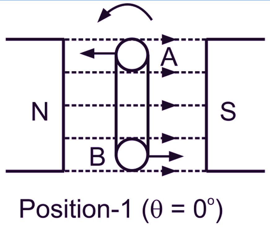
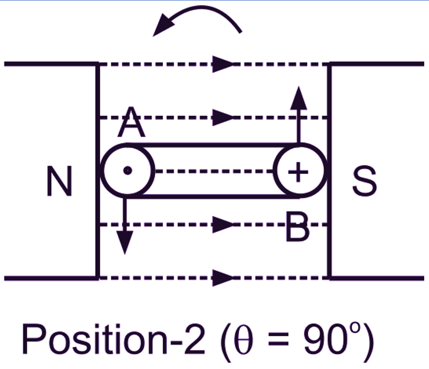
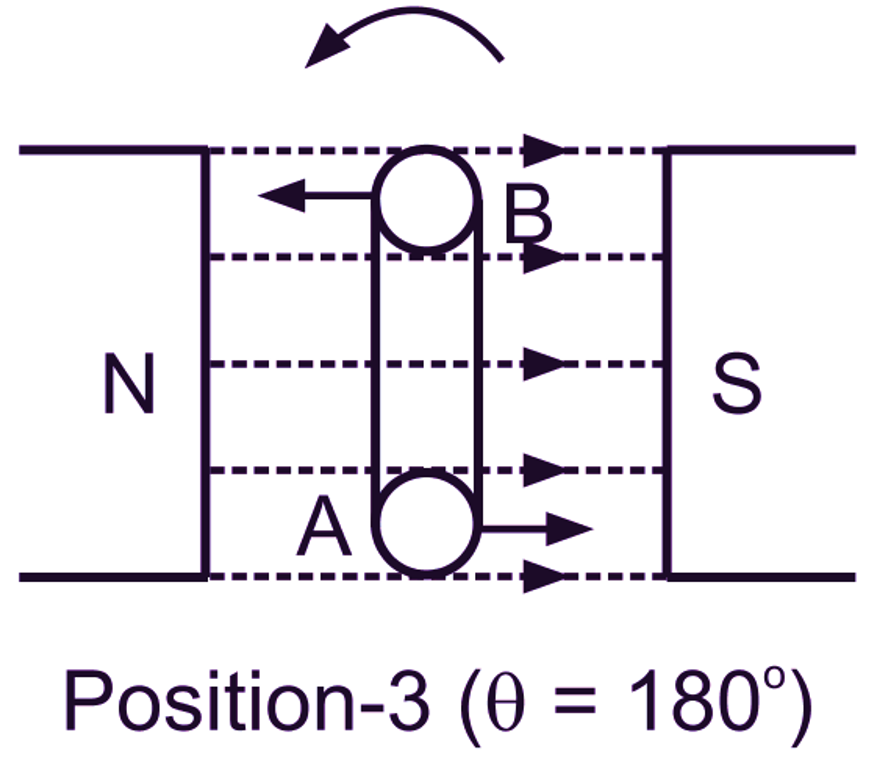
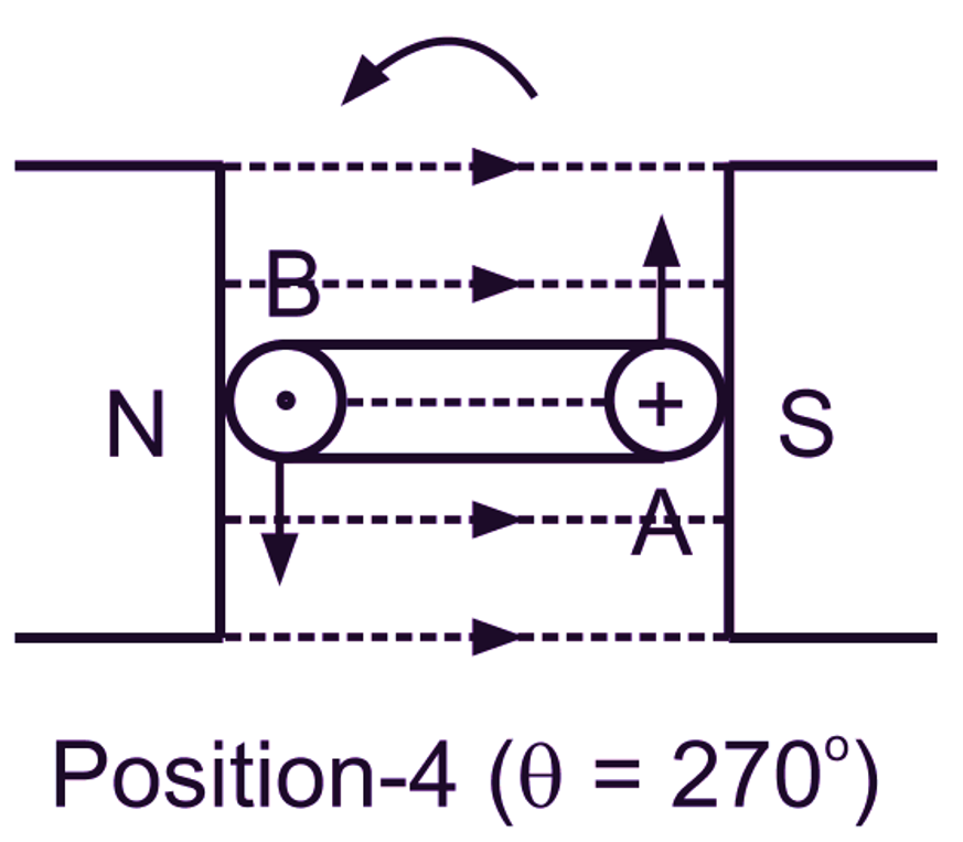
Fig. 2: The end views of the armature coil in different positions
Position No. 1: This is the initial position of the coil. The plane of the coil being perpendicular to the magnetic field, the conductors (A and B) Of the coil move parallel to the magnetic field. Since there is no flux cutting, no e.m.f. is generated in the conductors and, therefore, no current flows through the external circuit.
Position No. 2: As the coil rotates from Position-1 (θ = 0o) to Position-2 (θ = 90o), more and more lines of force are cut by the conductors. In the Position-2, both the conductors of the coil move at right angles to the magnetic field and cut through a maximum number of lines of force, so the e.m.f. induced in them is also maximum. In other words, between zero and 90o, the e.m.f. generated in the conductors builds up from zero to a maximum value. The e.m.f.s in both conductors being in series, the resultant coil e.m.f. is the sum of the two conductor e.m.f.s. It is therefore, twice that of one of the conductors, since the voltages are equal. The current through the circuit varies just as the e.m.f. varies, being zero at a 0° and rising to a maximum at 90o. In Position-2 Of the coil, according to Fleming’s right hand rule, the direction of the induced current in conductor A is towards the observer (i.e. out of the plane of paper) and in conductor B, it is away from the observer (i.e. into the plane of paper) as indicated. Therefore, the current flows through external resistor from the terminal C to the terminal D.
Position No. 3: As the coil continues to rotate further from Position-2 (θ = 90o) to Position-3 (θ = 180o), the lines of force cut by the conductors gradually reduce. This decreases the generated e.m.f. in them. In Position-3, the conductors again move parallel to the field and hence no e.m.f. is induced in them. Therefore, the current through the external resistor is also zero. It should be noted that during the rotation of the coil from 0o to 180o (i.e. during the first half revolution), the conductors of the coil move in the same direction through the magnetic field. Therefore, throughout this period, the polarity of the generated e.m.f. remains the same and current flows through the external resistor from C to D only.
Position No. 4: As the coil rotates beyond Position-3, the direction of the cutting action of the conductors through the magnetic field reverses. Now, the conductor A cuts up through the field and the conductor B cuts down through the field. In consequence, both the polarity of the generated e.m.f. and the current now reverse. To make it more clear, consider the coil in Position-4 (θ = 270o). By applying Fleming’s right hand rule, it is seen that direction of induced current in conductor A is away from the observer and in conductor B it is towards the observer. As such, current flows through the external resistor from D to C. Thus during the entire second half revolution i.e. when the coil rotates from the Position-3 to Position-4 and back to Position-I, the current flows in the opposite direction to that in the first half revolution. Also similar to Position-2, e.m.f. in the coil is maximum in Position4. In general, the variations in the magnitude of e.m.f. of the alternator when the armature coil rotates from 180o to 360o are exactly similar to those in the first half revolution. The graph of e.m.f. or current for the complete revolution of the coil under consideration is shown in Fig. 3.
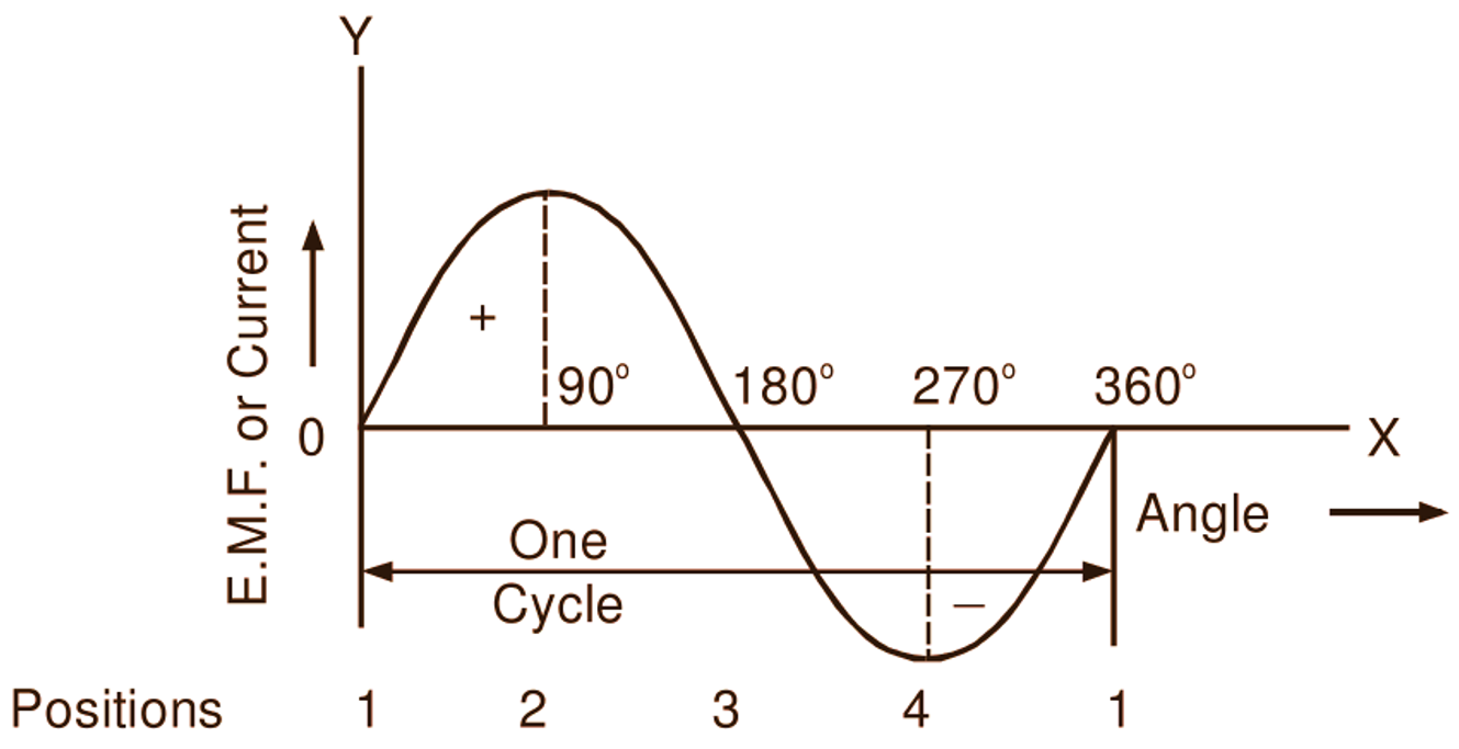
Fig. 3: Graphical representation of e.m.f. or current
From the above graph it will be readily seen that the voltage and the current supplied by such an alternator are alternating and follow a sine curve. In actual practice, the practical alternator has number of coils suitably connected to form one winding on the armature.