Single Phase Semi Converter provides only a one-quadrant operation. Most commercial applications need only controlled rectification and for this a Single Phase Semi Converter is enough.
Types of Single Phase Semi Converter
Generally, there are two types of configurations of semi-converter.
- Symmetrical Semi Converter.
- Asymmetrical Semi Converter.
Single Phase Symmetrical Semi Converter with R Load
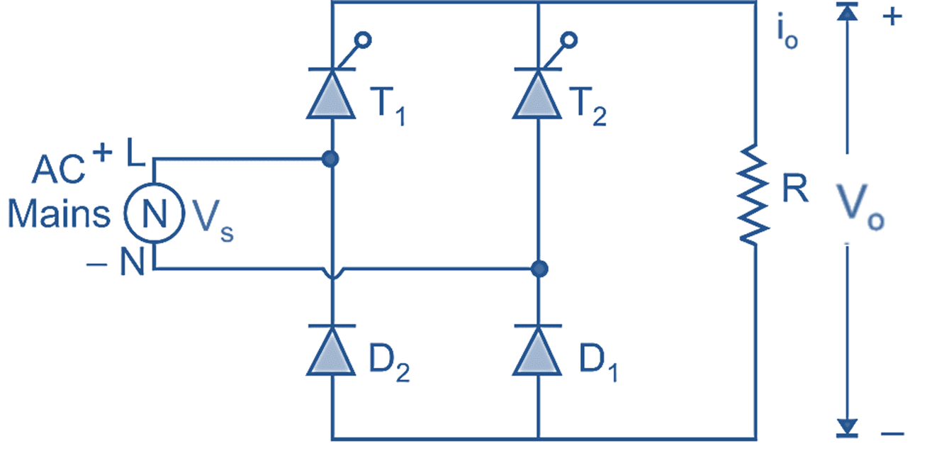
(a) Circuit Diagram.
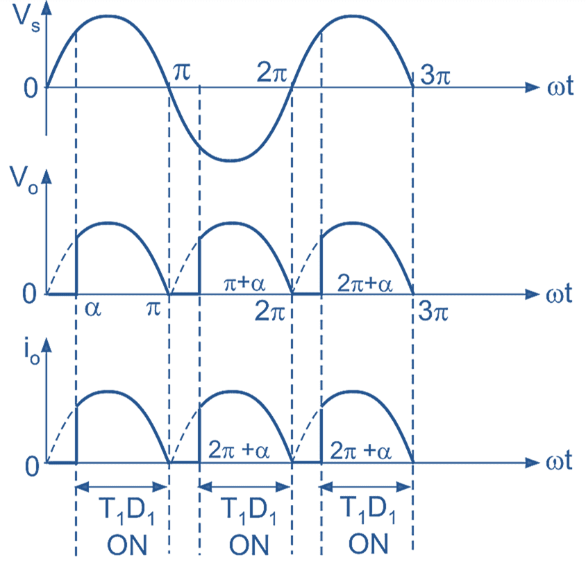
(b) Input, output voltage and current waveforms
Fig. 1: Single Phase Symmetrical Semi Converter with R Load
In Fig. 1 (a), shows the circuit diagram of single-phase half-controlled bridge rectifier with R load. In this rectifier two SCRs and two diodes are connected in symmetrical configuration.
The operation of this converter mainly consists of three modes:
Mode 1 :(α to π):
During positive half-cycle of AC input voltage, thyristor T1 and diode D1 conduct and thyristor T1 is fired at ωt = α. Therefore the average output voltage is equal to the instantaneous supply voltage and load current flows through T1 → R → D1 and back supply again.
Mode 2 : (π to π + α):
At instant ωt = π, the supply goes through zero and after π supply voltage reverses its polarity. Due to reverse supply across conducting devices T1 and D1, they turned off at ωt = π and this type of turn-off is called as “natural” or “line commutation”. Therefore, the average output voltage is zero (i.e. V0 = 0 volt) and load current is also zero.
Mode 3: (π + α to 2π):
At instant ωt = π + α, the supply voltage becomes completely negative i.e. during negative half cycle of AC input voltage, thyristor T2 and diode D2 are forward biased, thyristor T2 is fired at ωt = π + α. Thus the average output is equal to instantaneous supply voltage because due to conduction of T2 and D2, the load is directly connected to supply (i.e. V0 = VS). The load current flows through T2 → R → D2. Thyristor T2 and diode D2 conduct upto 2 π, at ωt = 2π commutation takes place due to natural zero appears across supply.
Advantages of Single Phase Semi Converter
- Improved power factor.
- Cost is reduced as 2 SCRs are replaced by 2 diodes.
- Reactive input power is reduced.
- Average output d.c. voltage is higher for same firing angle.
Disadvantages of Single Phase Semi Converter
- It can be operated only in rectification mode.
- Energy feedback from load to source is not possible.
Applications of Single Phase Semi Converter
Since it has a higher power factor, it can be used in high power applications. It is also widely used in main line a.c. traction where large d.c. motors are applied from a single-phase a.c. supply.
Formulas of Single Phase Semi Converter
Average value of output voltage (V0)
\[{{\text{V}}_{\text{0}}}=\frac{{{\text{V}}_{\text{m}}}}{\text{ }\text{ }\!\!\pi\!\!\text{ }\text{ }}\left( 1+\cos \alpha \right) \]
RMS value of output voltage (Vrms)
\[{{\text{V}}_{\text{rms}}}=\frac{{{\text{V}}_{\text{m}}}}{\sqrt{2}}{{\left[ \frac{\text{1}}{\text{ }\pi \text{ }}\left( \text{ }\pi \text{ }-\alpha +\text{ }\frac{\text{sin 2}\alpha }{\text{ 2 }}\text{ } \right) \right]}^{\text{1/2}}}\]