A continuous gate signal is not normally desirable to trigger SCR because of the associated power dissipation in the SCR, but in applications where the SCR may turn OFF before the time required this extra dissipation must be tolerated. The resistance is used to trigger SCR.
Circuit Diagram of Resistance (R) Firing Circuit (or Triggering Circuit) of SCR (Thyristor)
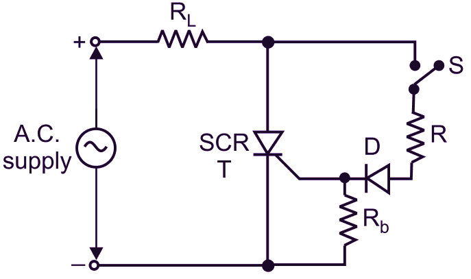
(a) Basic circuit
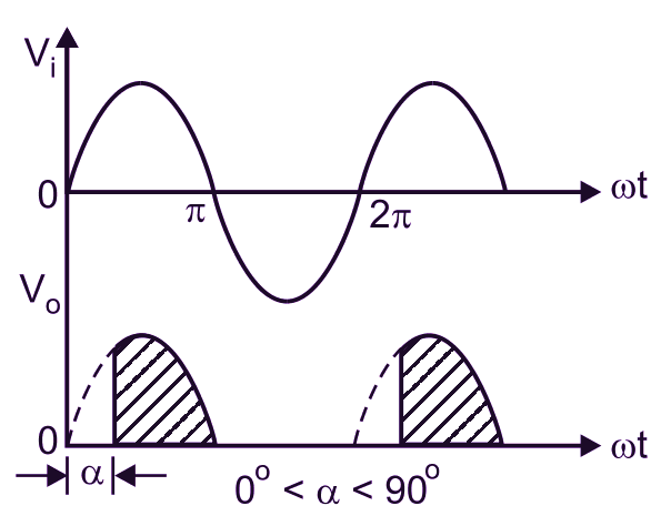
(b) Input and output waveforms
Fig. 1: AC gate resistance trigger circuit for an SCR
Fig. 1 (a) shows the circuit of an ac gate fixed resistance triggering for the SCR. The switch S may be of any type of mechanical switch (i.e. push button, read relay switch, etc.) initiated by manual control, or by heat, light, pressure etc. transducers or it could be a transistor switch. The resistance R is used to limit the gate current. The resistance Rb is used to improve the dv/dt rating of the SCR which prevents the undesirable triggering of the SCR. The resistance trigger circuit is also known as amplitude trigger circuit.
Principle of operation of Resistance (R) Firing Circuit (or Triggering Circuit) of SCR (Thyristor)
The ac voltage is applied between the anode and the cathode of the SCR. When the SCR is in the forward blocking state and the switch S is closed, the SCR turns ON and the output voltage appears across the load RL. The diode D is a blocking diode which is used as a preventive safeguard to the gate cathode junction from getting damaged, in the negative half cycle of the applied ac voltage. The tiring angle is limited to 90° only.
Practical Resistance Triggering
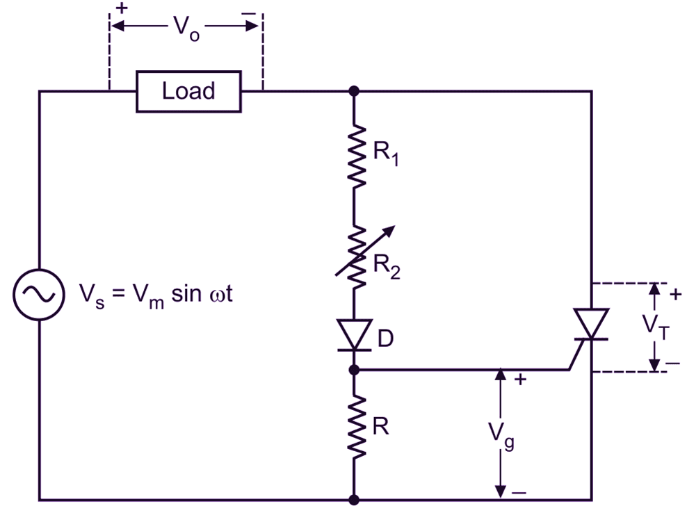
Fig. 2: Resistance triggering circuit.
In this circuit, R2 is the variable resistance to control the amount of gate current. The function of R1 is to limit the gate current to a safe value below maximum permissible gate current. Fig. 2 shows the most simplest and practical resistance triggering circuit.
Diode D allows the flow of current during positive half cycle only as SCR can conduct only during the positive half cycle when it’s anode is positive w.r.t. cathode. The value of R2 determines the gate voltage amplitude. The instant, at which SCR triggers or turns ON, is called as firing angle α. This firing angle is proportional to R2. As R2 is increased from small value, firing angle increases. In any case, a can never be more than 90°.
Waveforms of Resistance (R) Firing Circuit (or Triggering Circuit) of SCR (Thyristor)
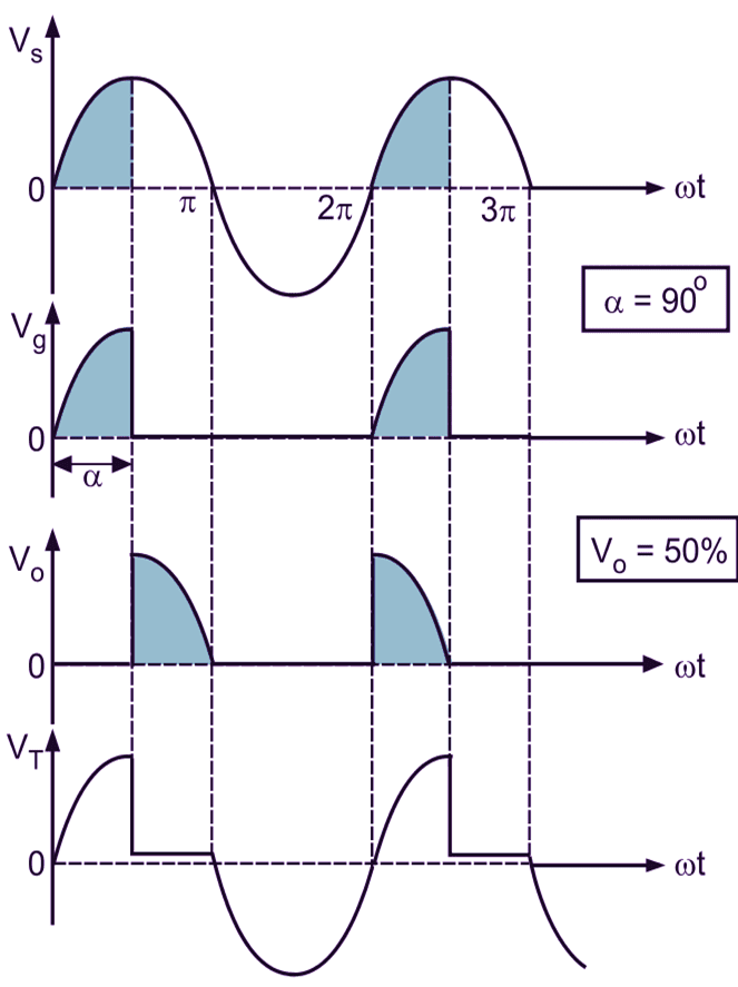
(a) α = 90°, R2 is high, V0 = 50
(b) α = 90°, R2 is small, V0 > 50
Fig. 3: Resistance trigger circuit waveform in half wave circuit with dc load Fig. 3 shows the output voltage waveform for different values of R2 set for α = 90° and α < 90°. Since the SCR will trigger and latch into conduction, the first time gate current reached the required minimum value to trigger SCR, its conduction cannot be delayed beyond 90° with this circuit. Therefore, this circuit provides continuously variable control for the SCR from full ON (100
The ac source is most commonly used for the gate signal in all applications of SCR control adopted for ac applications. The main advantages of this trigger circuit are as given below: The drawbacks (or limitations) of ac gate resistance trigger circuit are as under: The limited range of firing angle only upto 90° in the resistance trigger method of an SCR can be overcome by using RC trigger circuit. The limited range of firing angle can be increased from 90° to 180°, if the gate circuit of an SCR is supplied by a voltage that is shifted in its phase relationship to the anode voltage in such a manner that the positive gate current is sufficient to trigger the SCR can be delayed beyond the peak of the anode voltage.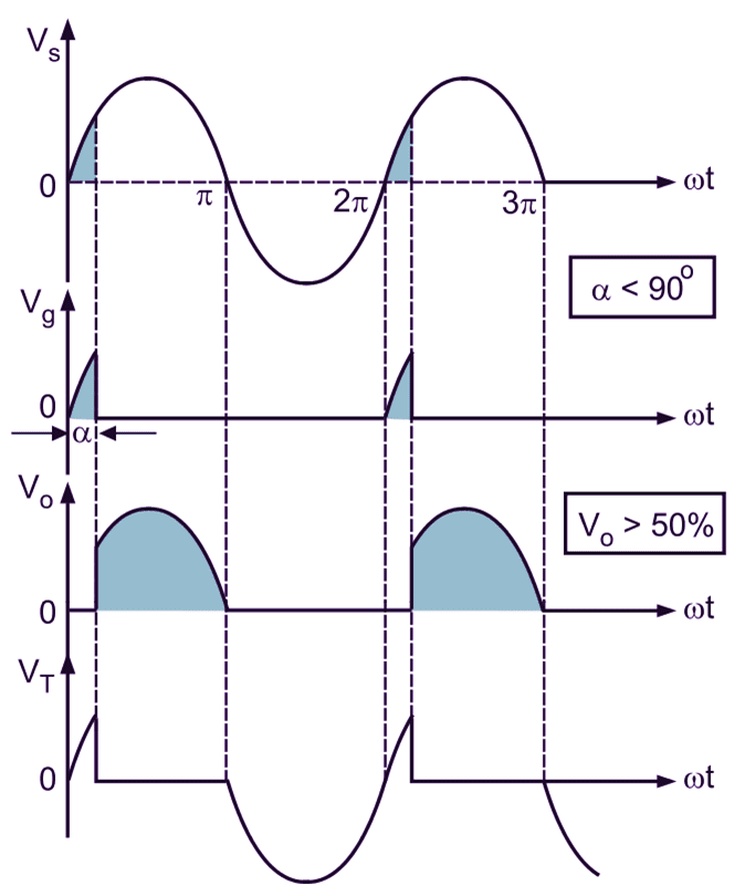
Advantages of Resistance (R) Firing Circuit (or Triggering Circuit) of SCR (Thyristor)
Demerits of Resistance (R) Firing Circuit (or Triggering Circuit) of SCR (Thyristor)
Remedy to Overcome Drawback