Single Phase Full Wave Controlled Rectifier is similar to Single Phase diode bridge rectifier but the only difference is that diodes are replaced by thyristors.
Types of Single Phase Full Wave Controlled Rectifier
The controlled bridge type converters are classified into two classes:
- Fully-controlled converter (Full converter).
- Half-controlled converter (Semi converter).
Single-Phase Fully Controlled Bridge Rectifier with R Load
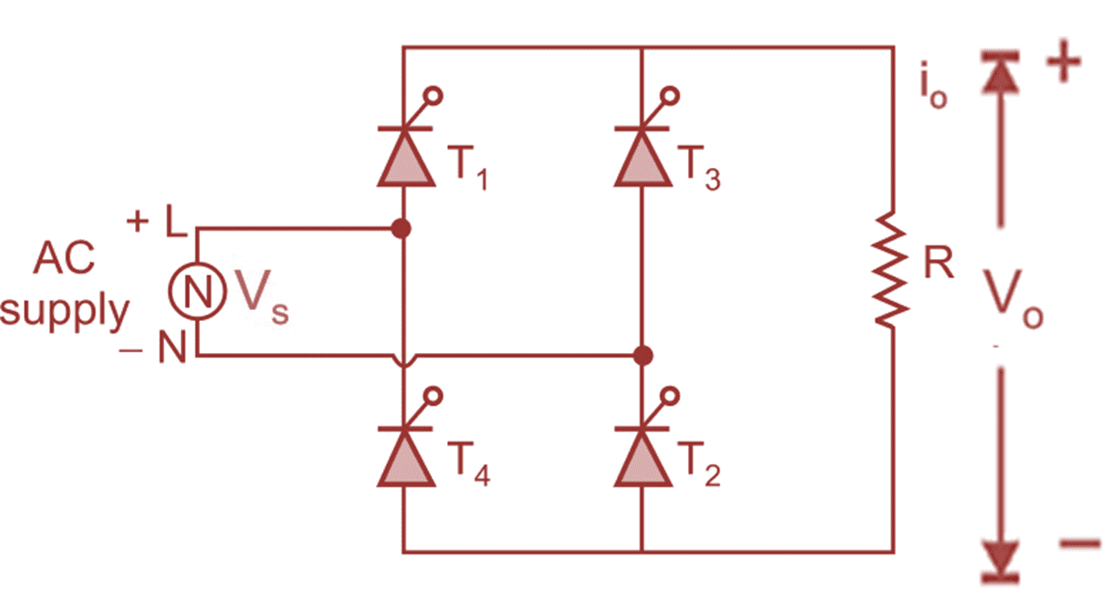
(a) circuit diagram
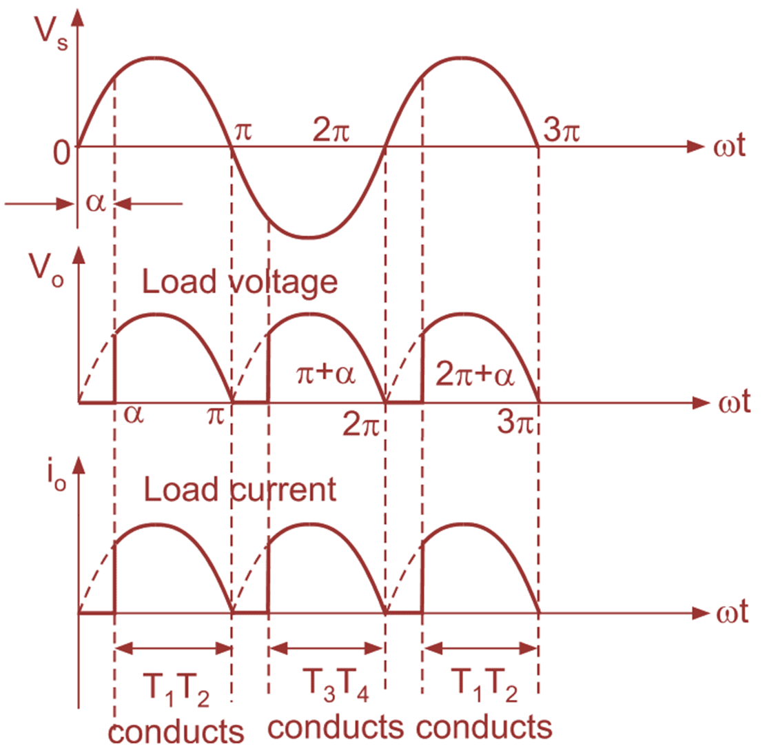
(b) Input and output voltage and current waveforms
Fig. 1: Single-phase fully controlled rectifier with R load
Fig. 1 (a) shows the typical circuit diagram of single-phase fully controlled bridge converter. It consists of four SCRs T1 to T4 and they are connected in bridge type configuration driving the resistive load.
The operation of single-phase fully controlled converter consists of three modes:
Mode 1 :(α to π):
At ωt = 0 instant, the supply voltage goes through zero, after ωt = 0, the supply goes towards positive, i.e. during positive half cycle of AC input voltage, thyristors T1 and T2 are fired at ωt = α, thus the average output voltage is equal to the supply voltage (i.e. V0 = VS). The current flows from point L through thyristor T1 through load resistance through T2 to point N. The load current is positive and has the same shape as that of AC mains input voltage. The load voltage and load current are in phase. At ωt = π instant, the supply voltage goes through zero, the conducting SCRs T1 and T2 are turned off due to natural commutation. At this instant, both load voltage and load currents are zero.
Mode 2 : (π to π + α):
At ωt = π, the supply becomes zero, after ωt = π the supply voltage reverses polarities. Therefore, in this mode of operation, no SCR conducts. Both load voltage and load currents are zero.
Mode 3: (π + α to 2π):
At instant ωt = π + α i.e. during negative half cycle of AC input voltage, the SCRs T2 and T4 are fired at ωt = π + α. Therefore, the load is directly connected to supply voltage and average output voltage is equal to the instantaneous supply voltage (i.e. V0 = VS). The load voltage is positive and load current is continuous positive. The SCRs T2 and T4 continue to conduct upto 2π. At ωt = 2π, the supply goes through zero, so conducting thyristors T2 and T4 will turn-off at ωt = 2π, due to line natural commutation.
Formulas of Single Phase Full Wave Controlled Rectifier
Average value of output voltage (V0)
\[{{\text{V}}_{\text{0}}}=\frac{{{\text{V}}_{\text{m}}}}{\text{ }\text{ }\!\!\pi\!\!\text{ }\text{ }}\left[ 1+\cos \alpha \right] \]
RMS value of output voltage (Vrms)
\[{{\text{V}}_{\text{rms}}}=\frac{{{\text{V}}_{\text{m}}}}{\sqrt{2}}{{\left[ \frac{\text{1}}{\text{ }\text{ }\!\!\pi\!\!\text{ }\text{ }}\left( \text{ }\text{ }\!\!\pi\!\!\text{ }\text{ }-\alpha +\text{ }\frac{\text{sin 2}\alpha }{\text{ 2 }}\text{ } \right) \right]}^{\text{1/2}}}\]