Synchroscope instrument is used to synchronize two alternators, which are to be connected in parallel with one another with bus bars to share the load. The synchroscope determines the exact instant where the conditions of synchronizing are satisfied. These conditions are:
- The alternators should have an equal magnitude of voltage. The voltages can be checked with the help of 2 voltmeters.
- They should have same frequency.
- And they should have same phase sequence. The function of this instrument is to indicate any difference in phase or in frequency. The phase sequence however is verified by a phase sequence indicator.
Types of Synchroscopes
The synchroscopes are the special form of power factor meters and are of two types:
- Electrodynamic type synchroscopes
- Moving iron type synchroscopes.
Electrodynamic (or Weston) Type Synchroscope
The Fig. 1 shows its simple construction. It consists of a three limb transformer and an electrodynamic instrument. The winding on one outer limb is connected with the bus bars and the winding on other outer limb is connected with the incoming alternator. The winding on the central limb of the transformer is connected to a lamp. The windings or the outer limbs produce two fluxes, which flow through the central limb, where the resultant flux is obtained which is the phasor sum of the two fluxes. This resultant flux induces an emf in the central limb winding.
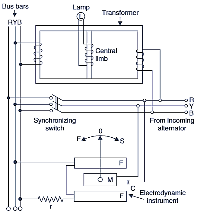
Fig. 1. Electrodynamic synchroscope
The outer windings are so arranged that when the voltages of the bus bar and of the incoming alternator are in phase, the two fluxes in the central limb are added up and induced eînf in the central limb is maximum as a result, the lamp glows with maximum brightness.
When the two voltages are 180° out of phase. the resultant flux is zero and no emf induced in the central limb winding, thus the lamp does not glow at all. If the frequency of the incoming alternator is different from the supply frequency of the bus bars, the lamp will flicker and the frequency of the flickering is equal to the difference of the two frequencies. But the flickering of the lamp cannot indicate whether the incoming alternator is fast or slow. For this purpose, an electrodynamic instrument is provided with the arrangement as shown.
The electrodynamic instrument consists of 2 fixed coils FF and a moving coil M. The fixed coils FF (See Fig. 1) carry a small current and are connected across any two bus bars through a resistance r. The moving coil M is connected across the incoming alternator through a capacitor C. The moving coil carries a pointer which moves on a scale showing fast/slow (FIS). The correct instant of synchronizing is that where the pointer is visible at its central position and is moving very slowly. The Fig. 2 show the dial of electrodynamic synchroscope.
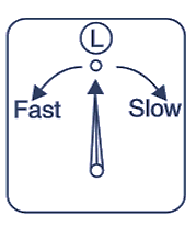
Fig. 2. Dial of the synchroscope
Moving Iron Type Synchroscope
This consists of a fixed coil in two parts. The fixed coils FF are designed for a small current and are connected across two phases of the bus bars (Fig. 3). There are two iron cylinders C1 and C2 mounted on a spindle and are separated by spacers. Each cylinder is provided with two iron vanes whose axes are 180° apart. The cylinders are excited by two pressure coils P1 and P2 which are connected to two phases of the incoming alternator.
One pressure coil has a resistance R and other lias au inductance L connected in series. It establishes a 90° phase difference between their currents. The pointer attached with the spindle moves over a dial marked fast and slow.
Operation: When the frequency of the incoming alternator is same as that of the bus bars, the instrument behaves as a moving iron PF meter. The movement of the pointer is equal to the phase difference between the two voltages. The pointer does not deflect at all if there is no phase difference between the two voltages.
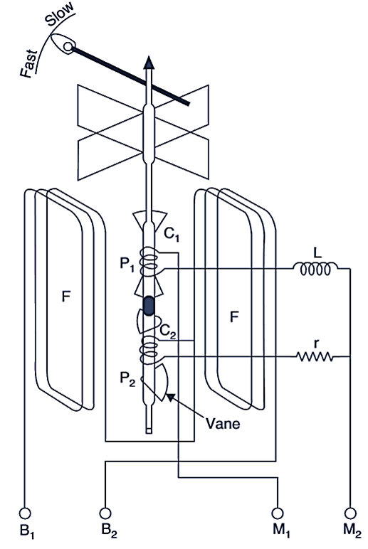
Fig. 3. MI type synchroscope
When the two frequencies are different, the pointer moves at a speed corresponding to the difference in the frequencies. The direction of motion of the pointer shows whether the alternator is fast or slow. When the pointer is at zero, the synchronizing switch is closed. The MI synchroscope are more common in use. They are cheaper and have a long scale spread over 360°.