In this topic, you study Three Phase Transformer Connections.
The primary and secondary windings of a three phase transformer or those of three single phase transformers forming a bank can be connected in different ways. We shall consider only few of these methods which are commonly employed in actual practice. They
- Star/Star connection.
- Delta/Delta connection.
- Star/Delta connection.
- Delta/Star connection.
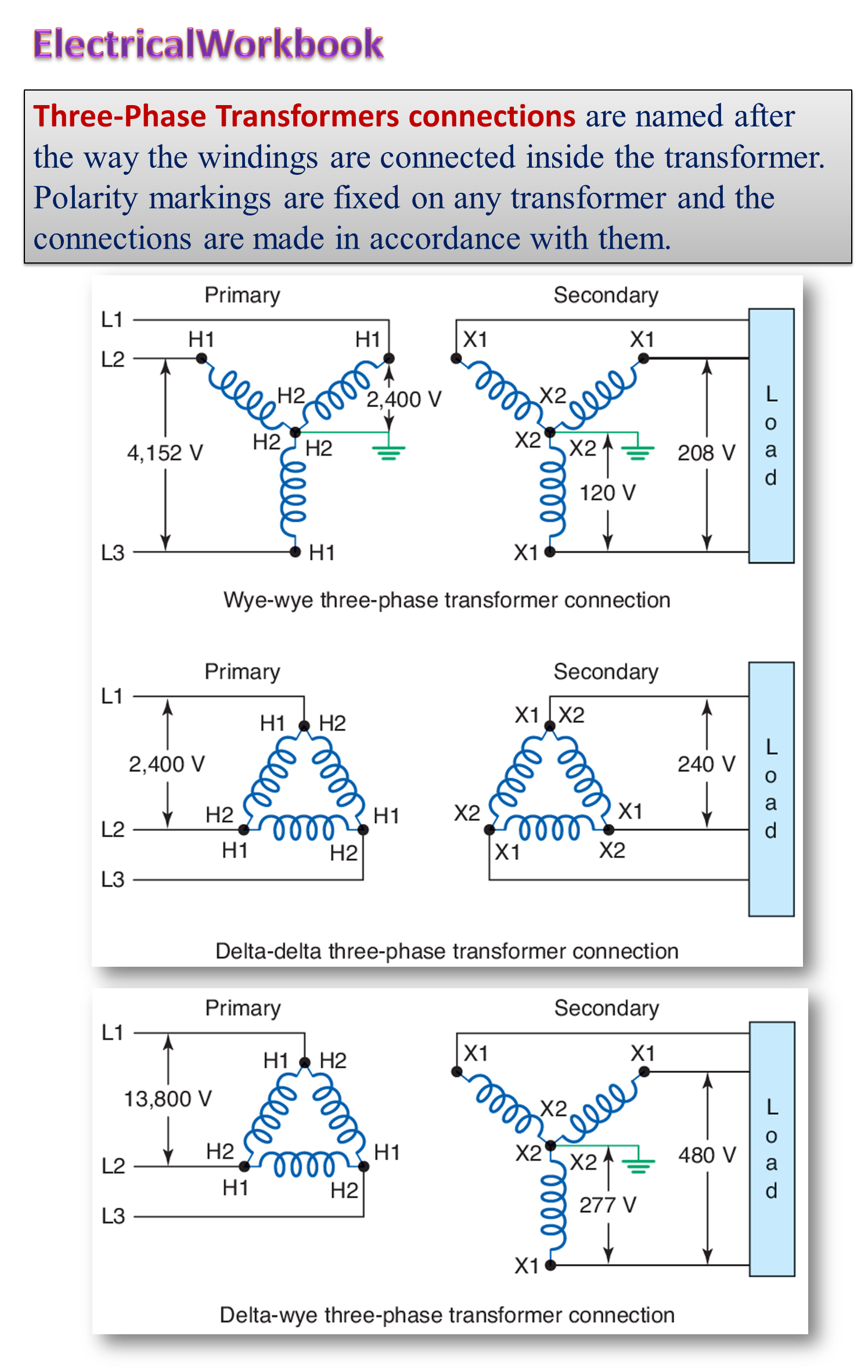
Nomenclature used for Three Phase Transformer Connections
While illustrating the above methods of connections with the help of suitable diagrams given below, the following nomenclature is followed: The h.v. terminals are labelled with capital letters such as A, B, C and the corresponding l.v. terminals with small letters such as a, b, c. The corresponding neutrals are labelled as N and n. The terminal polarities of the windings are indicated by suffixes 1 and 2. Thus, the terminals of the windings designated by the identical subscripts (i.e. 1 or 2) have identical polarities.
Star Star Connection
In this case, both the primary and the secondary windings are connected in star fashion. Fig. 1 shows such a typical star/star connection.
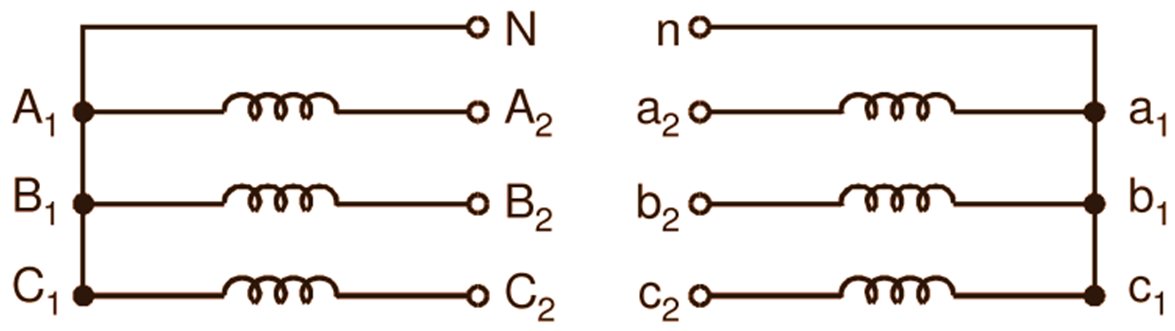
Fig. 1: Star/star connection
With this type of connection, the voltage per phase being 1/√3 times the line voltage, the transformer requires fewer turns per phase and less insulation. This makes the star/star connection the most economical connection for small high voltage transformers. The voltage per phase being low, the dielectric loss in the insulating materials is also low. Further, the phase current being equal to the line current, the wire with large cross-section is necessary for the winding. Therefore, the windings are mechanically strong and can easily withstand the severe stresses developed during the conditions of heavy load or short circuit. Due to availability of neutrals, adoption of a three phase four-wire system is possible. However, the performance of this type of connection is not satisfactory unless the load is balanced or, the neutral on the primary side is connected to the generator neutral. Hence, except for small high voltage transformers, the star/star connection is rarely used in actual practice.
Delta Delta Connection
In this case, both the primary and the secondary windings are connected in delta fashion. Fig. 2 shows the delta/delta connection.
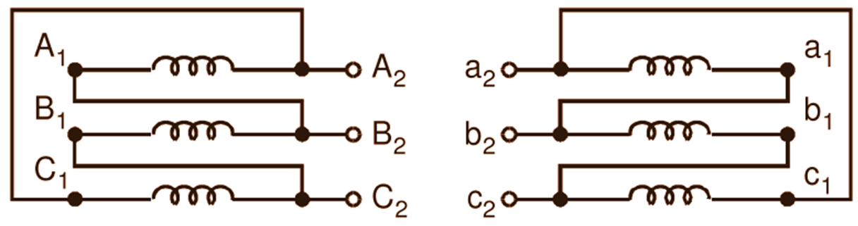
Fig. 2: Delta/delta connection
Even though this type of connection increases the number of turns per phase, it reduces the cross-sectional area of the conductors (as the phase current is 1/√3 times the line current). Hence for large low-voltage transformers in which the insulation problem is not much serious, considerable saving can be effected by the use of this type of connection. Further, with this connection, the loads with large unbalance can be met without much difficulty. With a bank of three single phase transformers using this type of connection, the system can operate at 58
Star Delta Connection
In this case, the primary windings are connected in star and the secondary windings are connected in delta as illustrated in Fig. 3.
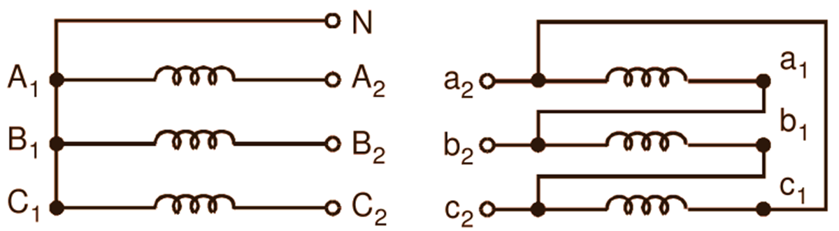
Fig. 3: Star/delta connection
c,
Star/delta connection is very common for large high voltage, step-down power transformers, generally used at receiving end substations. Use of star connection on h.v. side results in saving in cost of insulation. The neutral available on h.v. side is used for grounding. This type of connection gives satisfactory performance inspite of large unbalance of loads.
Delta Star Connection
This connection is just the reverse of star/delta connection i.e. in this case, the primary windings are connected in delta and the secondary windings are connected in star. The diagram of connection is shown in Fig. 4.
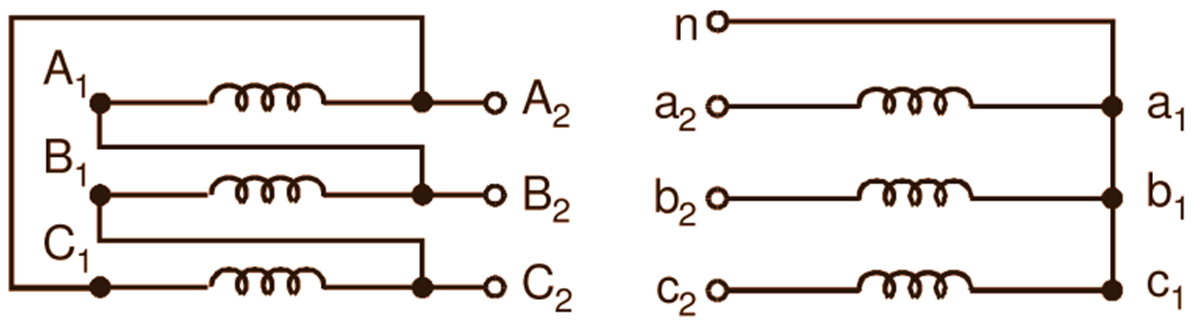
Fig. 4: Delta/star connection
This connection is very common for large high voltage, step-up power transformers used at generating stations with h.v. windings connected in star for saving in the cost of insulation. In such cases, the neutral available on the h.v. side is used for grounding. This connection is also commonly employed for step-down distribution transformers as the star connection on I.V. side permits mixed loading with three phase and single phase loads, while delta connection on h.v. side allows the flow of circulating current to compensate for neutral current on the star side. Therefore, the large unbalance of loads can be met without difficulty.
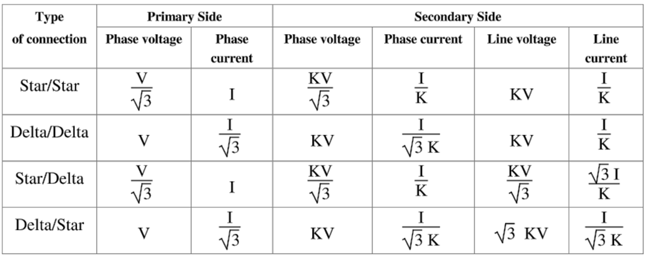
VOLTAGE AND CURRENT RELATIONSHIPS FOR DIFFERENT TYPES OF TRANSFORMER CONNECTIONS
In the case of three phase transformers or banks of three single phase transformers, the phase voltage ratio is obviously the same as the turns ratio, but the ratio of the terminal or line voltages depend upon the method of connection employed. Relationships between the voltages and currents on the primary and secondary sides with different types of transformer connections are shown in the tabular form below in the Table 1. The following assumptions have been made while deriving these relationships:
(i) Primary line voltage = V
(ii) Primary line current = I
(iii) Phase transformation ratio,
\[\frac{{{\text{V}}_{\text{2}}}}{{{\text{V}}_{\text{1}}}}=\frac{{{\text{N}}_{\text{2}}}}{{{\text{N}}_{\text{1}}}}=\text{K}\]
(iv) Loads are balanced and have unity power factor.
(v) Transformers are ideal with no losses.
Table 1