In this topic, you study Three Phase Transformer – Theory, Diagram, Advantages & Disadvantages.
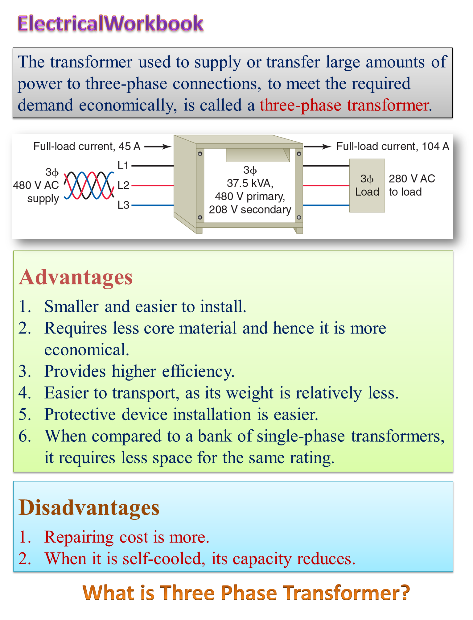
The transformers are designed to operate on three phase supply are known as three phase transformers.
Transformation of three phase alternating current from one voltage to another can be carried out either by using a single unit of three phase transformer or a bank of suitably connected three separate single phase transformers. In practice, for three phase circuits, use of a three phase transformer is generally preferred over a bank of three single phase transformers. The pictorial view of three phase transformer shown in Figure 1.
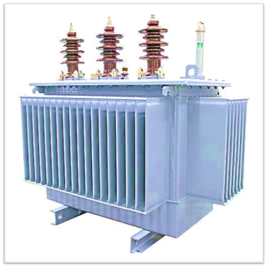
Fig. 1: Three phase transformer pictorial view
Working Principle of Three Phase Transformer
To understand the operation of a three phase transformer, consider three single phase transformers (secondaries eliminated for clarity) arranged as illustrated in Fig. 2, with their cores at 120o and touching each other. The primaries of these transformers are connected to a three phase ac supply. As a result, the cores are magnetized and the centre leg formed by the three cores carries the sum of the three fluxes Φ1, Φ2, and Φ3 produced by the three phase currents I1, I2, and I3 respectively.
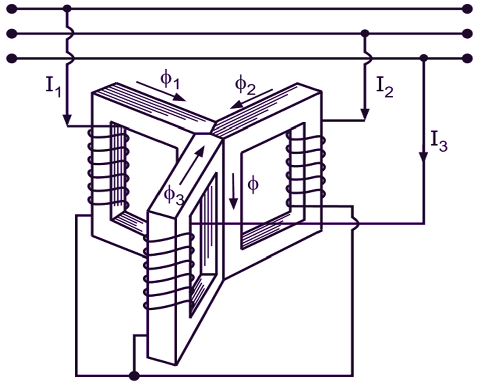
Fig. 2: Principle of a three phase transformer
As the sum of these three currents (differing in phase by 120o) at any instant is zero, the sum of the three fluxes meeting in the common leg must also be zero. Hence, the common leg which carries no appreciable flux can be safely eliminated without disturbing the other conditions. This is because under such a condition, any two legs can provide the return path for the flux in the third leg. From the point of view of core construction, this is the principle adopted in the case of a three phase transformer. It considerably reduces the size and weight of a three phase transformer. The actual shape of the core used depends on the type of the transformer.
Selection of a Three-phase Transformers
The criteria for selection of a three-phase transformer depend on its intended use, working conditions and operating requirements. The following are considered as the main governing features for the selection of three-phase distribution as well as power transformers.
Ratings: This includes the kVA rating , nominal sy’stem voltage, no-load voltage ratio and frequency. In order to reduce varieties for the purpose of standardization, the kVA rating of the transformer shall be selected from the specified standard ratings. For the transformers to be operated in parallel with other transformers, the no-load voltage ratio should be selected in accordance with the necessary requirements. The kVA rating means steady kVA that can be carried by a transformer continuously without exceeding the specified limits Of temperature rise while operating under normal service conditions (ambient temperature, humidity, altitude, etc).
Type of Construction: Two main types of transformers are available, namely liquid-filled and dry-type. The liquid-filled (those filled with either transformer oil or an insulating liquid specially designed for transformers) transformers are more efficient, have greater overload capacity and longer life. But they have a greater risk of inflammability than dry-type transformers. Dry-type transformers are usually used for lower power ratings. Lower capacity indoor transformers are typically dry type, whereas high capacity transformers used outdoors are almost always liquid filled.
Core Material: The choice of core material is a crucial consideration in the selection process of transformers. The core shall be made up of high grade cold rolled grain oriented (CRGO) annealed steel laminations having low loss. The core can also be wound type using high quality amorphous metal ribbons with very low loss.
Winding Material: Choosing proper winding material is also of vital importance while selecting a transformer. Aluminium-wound units are typically less expensive and usually the most cost-effective. Copper-wound transformers, however, are smaller because copper is a better conductor and it also contributes to the coil’s greater mechanical strength. Hence, for large capacity transformers (above 100 k VA), copper is preferred as a winding material over aluminium.
Taps: Even with good regulation, secondary voltage of a transformer can change if the incoming (primary) voltage changes. To compensate for such voltage changes, transformers are often built with no-load tap changers (NLTCs) or on-load tap changers (OLTCs). OLTCs can operate with the load connected, whereas NLTCs are to be operated only when the load is disconnected. These devices consist of taps or leads connected to either primary or secondary winding at different locations which make it possible to slightly change the turns ratio and thereby supply a constant voltage from the secondary winding to the load under varying conditions. It is important to correctly assess the requirement of voltage taps during the selection process of transformers.
Connection Symbol: Another consideration when selecting the transformers is the manner in which they are to be connected to the system. The preferred connections for two winding transformers are delta/star (Dy), star/star (Yy), star/delta (Yd). Selection of exact connection symbol and group should be made taking into consideration the requirements of parallel operation with other transformers.
Impedance: Transformers with lower impedance have lower voltage drops but allow higher fault currents. The transformer impedance is chosen taking into consideration the secondary fault levels, available rating of the switchgear on the secondary side and associated voltage drops.
Termination Arrangements: The arrangement for termination of primary and secondary terminals shall be such that cables are not required to be terminated to the bushing studs directly. Cable box when used shall be separately supported and detachable type so that the transformer can be taken out for maintenance without removing the cables.
Cooling: The type of cooling may be AN, ONAN, ONAN/ONAF, ONAN/ONAF/ONWF depending upon the type and size of the transformer required.
Fittings and Accessories: These mainly include oil level gauge, winding temperature indicator, oil temperature indicator, breather, explosion vent, gas and oil actuated relay, drain-cum-sampling valve for oil, etc.
Insulation Level: The insulation level of a transformer is based on its basic impulse level (BIL), defined as the maximum peak voltage that a piece of equipment can withstand before its insulation breaks down. The BIL must be carefully selected for a transformer.
Performance Requirements: Efficiency and regulation requirements must be evaluated carefully during the selection process of transformers to ensure that the transformer selected meets the necessary needs.
Write the advantages and disadvantages of three-phase transformer star and delta connections?
Three phase transformer can either be connected in star or in delta. These are the possible connections as shown in Fig. 18.18.
Fig. 18.18. Different connections of 3 phase transformers.
Advantages of star connections:
- In star connections the line voltage is equal to the √3 phase voltage. Therefore the insulation required for phase winding will be of less dielectric strength.
- Less phase voltage means less number of turns i.e. less copper is required i.e. cost is less.
- In star the neutral point is obtained, so three phase four wire supply can be taken to distribute the lighting and power load simultaneously. The secondary Of the distribution transformer is connected in star.
Advantages of delta connections:
- In delta connections if one phase fails the three phase supply will be continued to the load but with a reduced efficiency.
- In open delta connections the efficiency decreases to 57.7
- These connections are efficiently used for transmission transformer, only three wires are required to transmit the power thus reducing the cost of the transmission lines.
What do you understand by the three phase transformation? How it is obtained?
To transform the three phase voltage from one level to the another level, is known as three phase transformation. It can be obtained by these following methods:
(a) By using three single phase transformers.
(b) By using one transformer of three phase.
By using three single phase transformers. In this case three single phase transformers are used. These are identical in voltage ratio and capacity. The primaries and secondarius of all the transformers can be connected in star/star, star/delta, delta/star, delta/delta. The group of the transformers so connected is called the bank of transformers. The bank in star/star is shown in Fig.1 18.19.
Advantages
In Case of any fault in one phase only one transformer is required to change. Thus one transformer is required in spare.
Disadvantages
- More cost of the three transformers.
- Requires more space and more maintenance.
- Has more weight and the installation cost of the bank is more.
- Nowadays these methods are not so popular.
Using single unit of three phase This system of transformation is commonly used at-present. In this system only one transformer is used. The windings can be connected either in star or in delta depending upon the requirement.
Fig. 18.20. transformer.
Advantages:
- It requires less maintenance.
- Iess cost than three transformers Of single phase.
- Less space is required and have less weight.
Disadvantages. In case of any fault and break down, even in one phase the complete set in required in spare to replace.