In this topic, you study Variable Reluctance Stepper Motor – Working, Circuit Diagram & Construction.
Variable Reluctance Stepper Motor is the most basic type of stepper motor.
Construction of Variable Reluctance Stepper Motor
Fig. 1 schematically represents such a motor. The stator usually made of laminated silicon steel has six salient poles or teeth and is wound for three phases located 120⁰ apart. The two coils wound around diametrically opposite poles and connected in series form a stator phase. The three phases thus formed are energized from a dc source in a specified sequence through an electronic switching device. The rotor is also normally made of silicon steel laminations and has four salient poles (or teeth) without any exciting winding as shown.
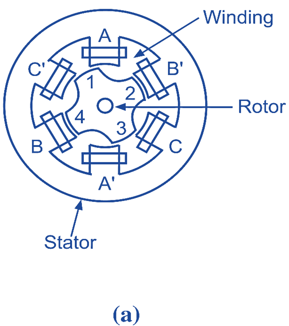
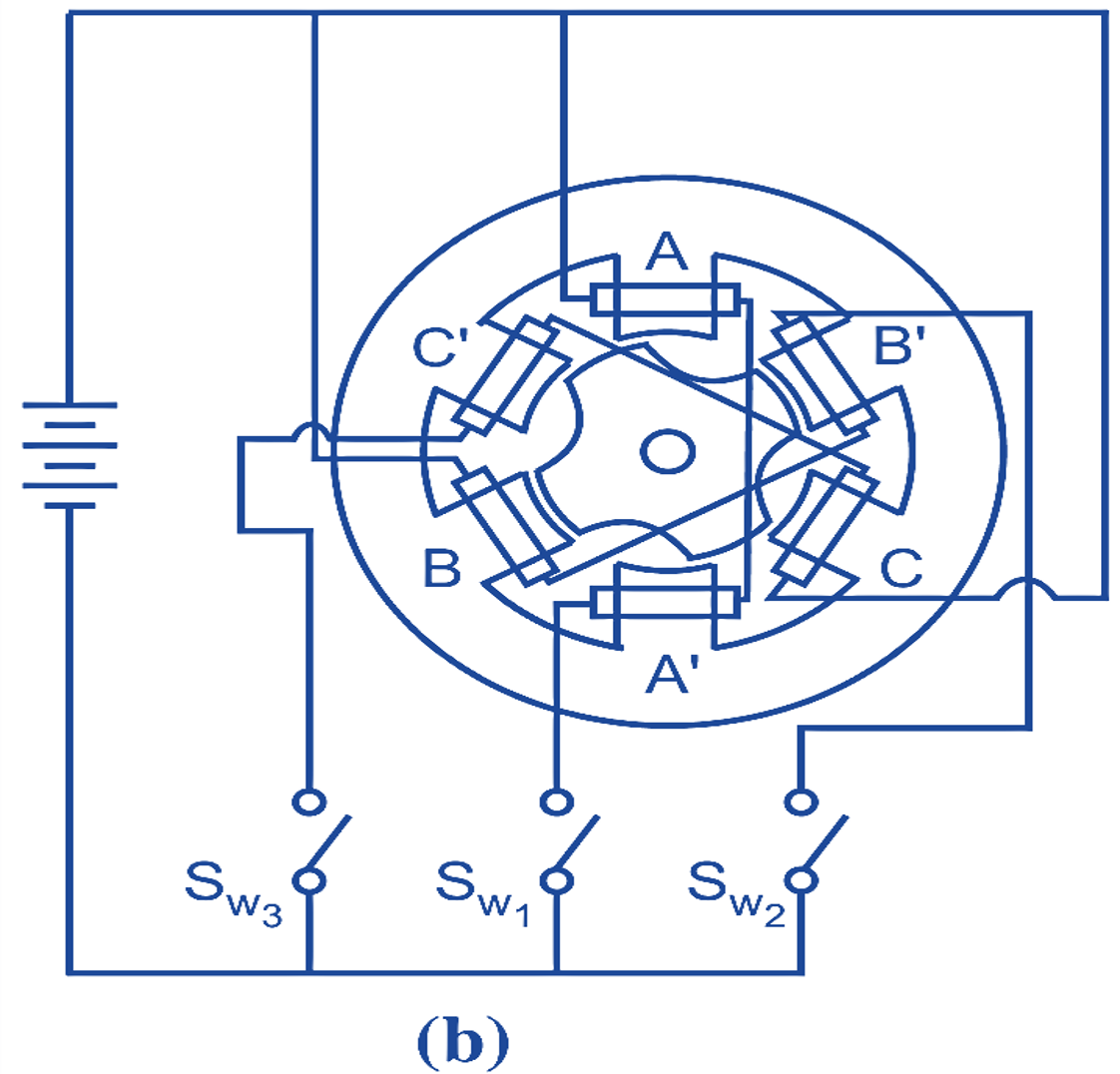
Fig. 1: Schematic representations of a variable-reluctance stepper motor (a) Cross-sectional view. (b) Winding arrangement.
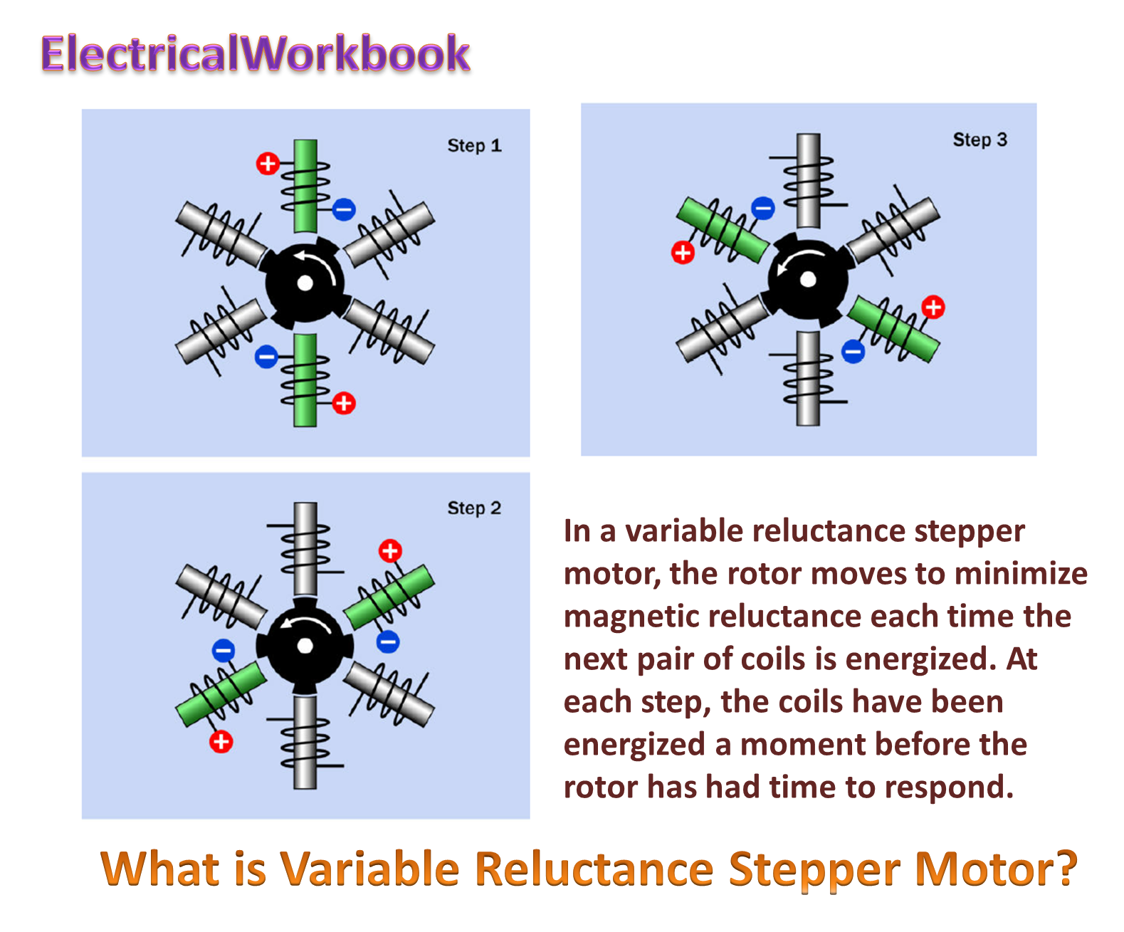
Working of Variable Reluctance Stepper Motor
When phase A is excited (with coil A forming a North-pole and coil A’ forming a South-pole), the rotor in its attempt to seek the position of minimum reluctance between the stator and rotor, is subjected to an electromagnetic torque and thereby rotates until its axis coincides with the axis of phase A (Fig. 2 a). If now, phase B is excited (with coil B forming a North-pole and coil B’ forming a South-pole), disconnecting the supply to phase A, the rotor will move through 30o in an anticlockwise direction and take up the minimum reluctance position shown in Fig. 2 (b). Next, if phase C is energised while disconnecting the supply to phase B, the rotor will move through another 30o in an anticlockwise direction and take the position indicated in Fig. 2 (c). Thus, if three phases are successively excited in the above manner by supplying the voltage pulses, the motor will take one Step of 30o with each voltage pulse and will require 12 pulses to make one complete revolution.
Further, it will be observed that if the three stator phases are supplied with voltage pulses adopting a switching sequences as A – C – B – A – …., the rotor will move in the clockwise direction.
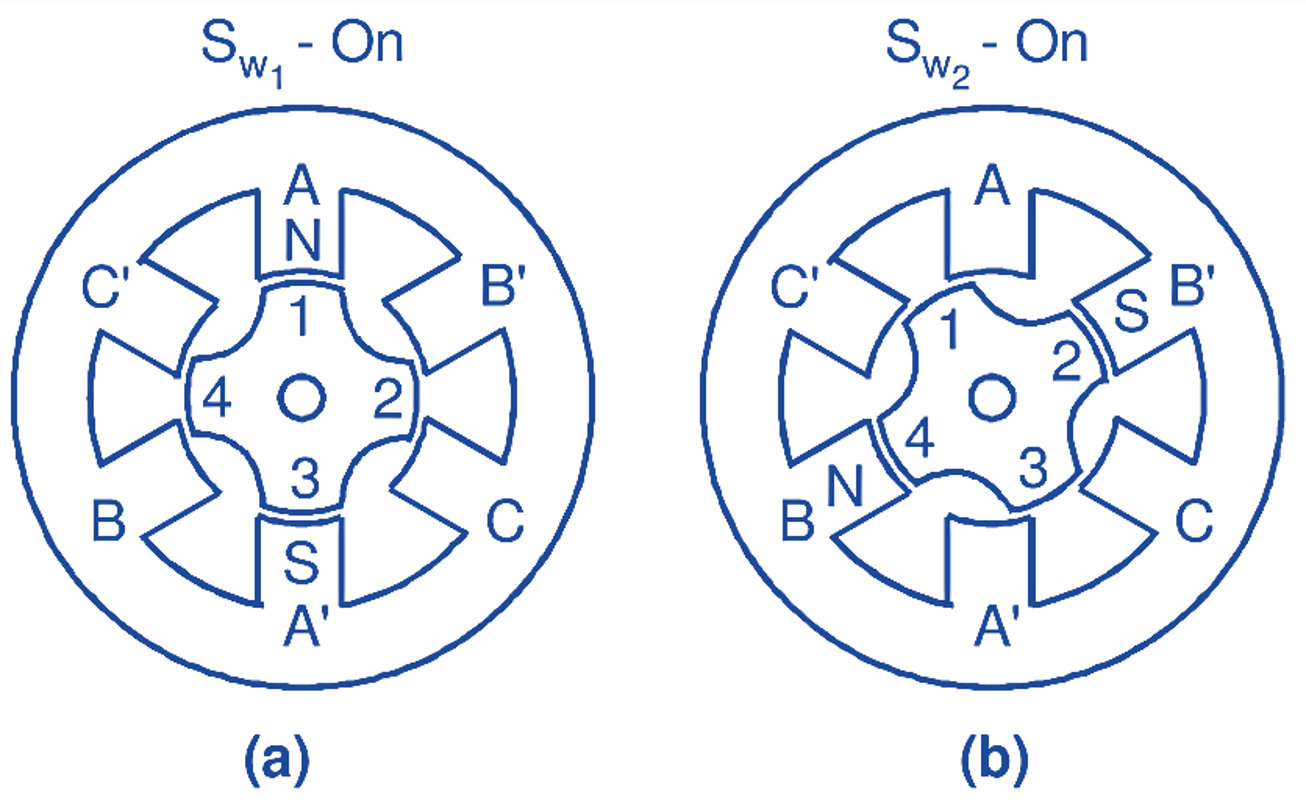
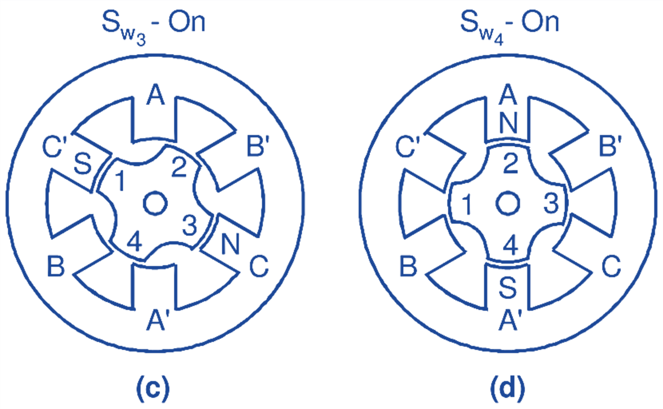
Fig. 2: Step motions as switching sequence proceeds in a three-phase variable-reluctance stepper motor.
Reduction in Step Angles of Variable Reluctance Stepper Motor
The 30o step angle obtained in the motor of Fig. 1 is not a small angle. It can be shown that if the rotor of the motor under consideration had 8 salient poles, the rotor would move 15° for each voltage pulse. Thus, with 8 rotor poles and stator wound for three phases, 24 steps would be required for making one complete revolution. A further reduction in step angle can be achieved either by increasing the number of poles of the stator and rotor or by adopting different constructional techniques such as :
- Using reduction-gear stepper motor.
- Using multi-stack or cascade type stepper motor.
Using Reduction-Gear Stepper Motor
Fig. 3 shows the cross-sectional view of this type of variable-reluctance motor. The stator has 8 salient poles and is wound for 4 phases. Each salient pole Of the Stator has two teeth. The rotor has 18 equally spaced teeth. The general relationship between step angle θS, number of stator phases m and rotor teeth Nr is given by
\[\theta {{}_{\text{S}}}\text{ = }\frac{\text{36}{{\text{0}}^{\text{o}}}}{\text{m }{{\text{N}}_{\text{r}}}}\]
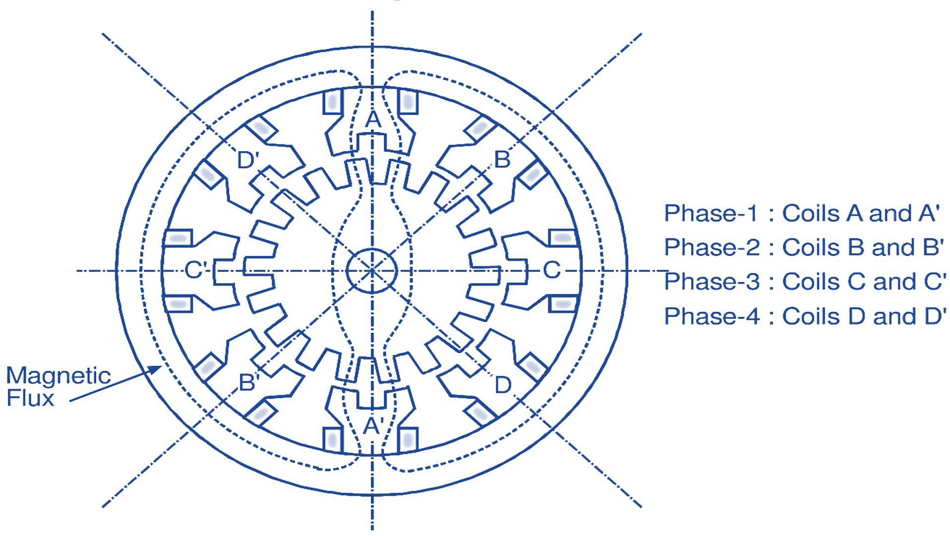
Fig. 3: Reduction-gear stepper motor (with phase-I excited)
Hence, with the type of construction shown in Fig. 3, motor will have step angle of 5
Using Multi-Stack or Cascade type Stepper Motor
The variable-reluctance motors shown in Figs. 1 and 3 are single-stack type motors. An outstanding feature of this type of motor is that three or four phases are arranged in a single stack i.e. in the same plane. Another type of variable-reluctance motors is the multi-stack type or cascade type. Fig. 4 shows a three stack (sometimes also called 3-phase) motor.
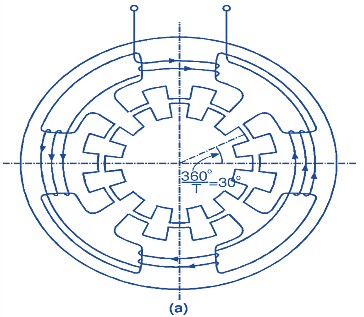
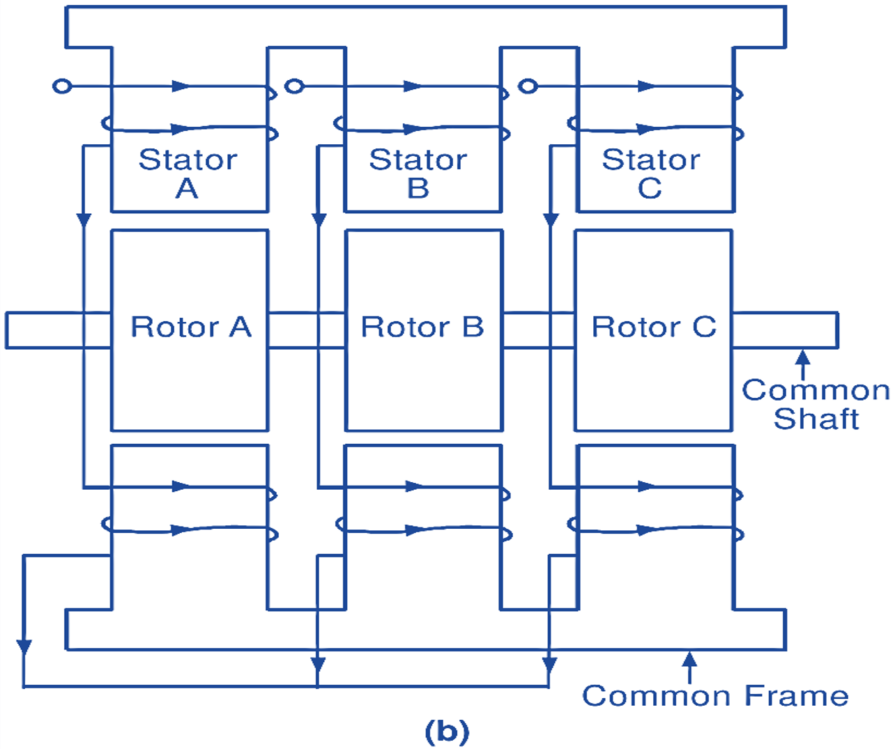
Fig. 4 : (a) End view of stator and rotor of one stack of a variable-reluctance motor, (b) Longitudinal cross-sectional view of a 3-stack variable reluctance motor.
In this type of motor, both stator and rotor have a toothed structure with the same tooth pitch. The stators of the three stacks have a common frame while the rotors have a common shaft. The teeth of all the rotors are perfectly aligned with respect to each other, while the stator teeth of various stacks are arranged to have a progressive angular displacement of
\[\text{ }\!\!\beta\!\!\text{ }\text{ }\text{= }\frac{\text{36}{{\text{0}}^{\text{o}}}}{\text{qT}}\]
where, q = Number of stacks, T = Number of teeth
To begin with, let us assume that the winding of stator C is excited and the stator and rotor teeth in that stack are in alignment for minimum reluctance. Obviously, at this moment, the teeth of both the members of other stacks will be misaligned due to progressive angular displacement of between the stator stacks. Now, if the excitation is switched from the winding of stator C to the winding of Stator A, the rotor will move by angle β so that the stator and rotor teeth of that stack are aligned. Next, the excitation of the winding of stator B will cause further movement of the rotor through β. Thus, if the Stator windings are excited in sequence A – B – C – A -…., the rotor moves in steps of β in one direction. The direction of rotation will be reversed if the switching sequence is changed to A – C – B – A -…..,
Typical step angles of stepper motors are 15o, 7.5o, 2o, and 0.72o, the choice being dependent upon the angular resolution required for the particular application.