There are so many mechanical activities to be performed for domestic, commercial and industrial work with the help of electrical operated machines. The applications like transportation, rolling mills, washing machines, fans, pumps, textile work, robots need electrical drives.
Definition of Drives
The systems employed for motion control are called as ‘drives’.
Definition of Electric Drives
It is defined as an electromechanical device for converting electrical energy into mechanical energy to impart motion to different machines and mechanisms for various kinds and process control. And this may employ any of the prime movers like – Hydraulic, steam engine, gas-steam turbines, diesel-petrol engines and most common drive is “Electric Motor”. Electric motors are treated as “Electric drives”.
Necessity of Electric Drive/Benefits
The electric drive is necessary because of following reasons
Improvement in efficiency: The effective control of power fed to motor gives better efficiency.
Starting current control: It can effectively control the starting current to a safe value. The motor can then start with safe value of current.
Precise control: The speed control is precise due to use of power electronic devices.
Protection: It avoids adverse operating conditions, hence the motor is protected.
Advance control: It takes care of other factors like temperature, pressure variations etc.
Block Diagram of Electric Drive and Main Components (i.e. Parts)
Components are electric drive are :
- Source.
- Power modulator.
- Motor.
- Control unit.
- Sensing unit.
- Load.
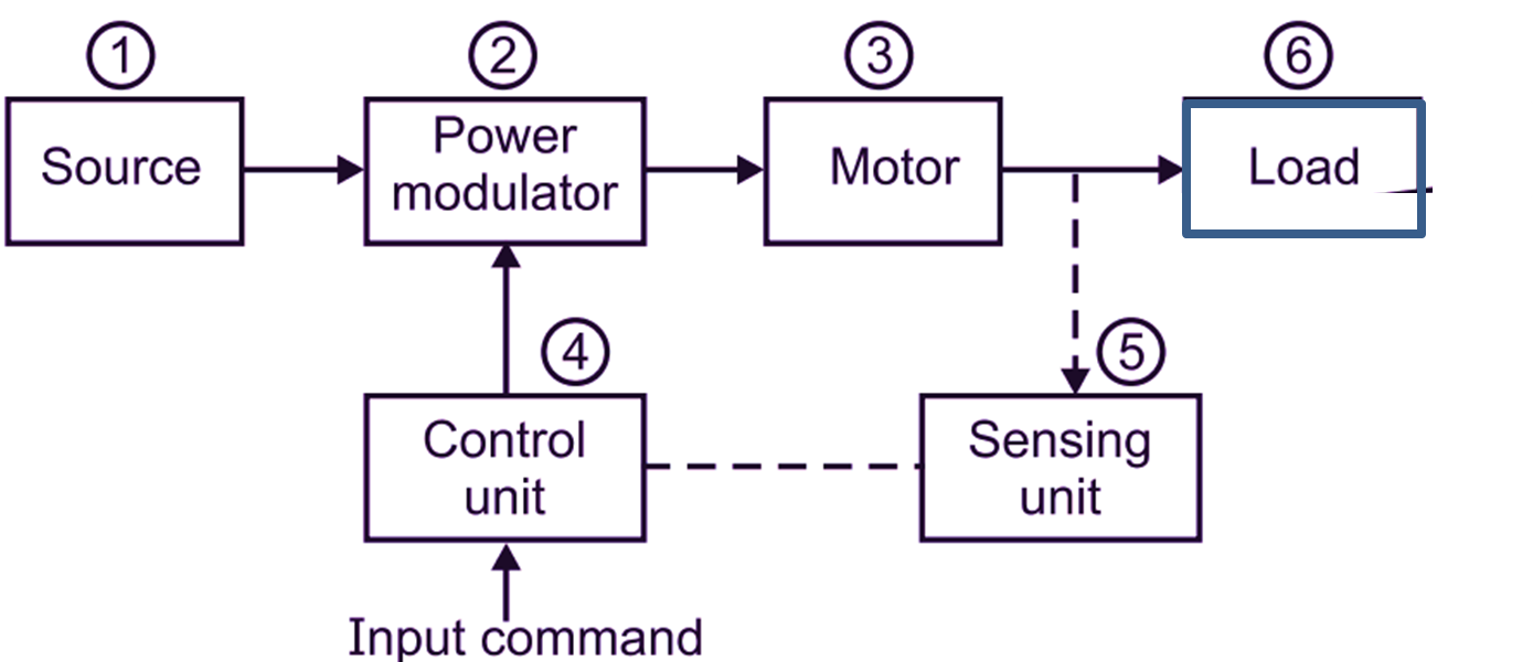
Fig. 1: Block diagram of an electric drive
Operation of an Electric Drive
Load
It is usual a machinery designed for accomplishing a given work (task). It is like pumps, robot, washing machines, machine tool, drills etc.
Power modulator and its functions
- Power modulator modulates the flow of power from the source to the motor. See the block diagram. It is connecting source and motor.
- It acts as a rectifier or inverter i.e. if source is A.C. and motor is D.C., it converts A.C. into D.C. acting as a rectifier. If source is D.C. and to be connected to induction motor operating on A.C., it acts as an inverter to change D.C. into A.C. of variable frequency.
- In operation such as starting, braking, speed reversals, it restricts source and motor currents with the permissible range (margins).
- It helps in selecting the mode of operation of motor i.e. motoring or braking.
Working Principle of Drives and Function of Parts of Drive
It is an electromechanical device which converts electrical energy into mechanical energy to impart motion to different mechanisms involved in process control.
General Block Diagram Of Electric Drive
The block diagram of electric drive is shown in Fig. 2.
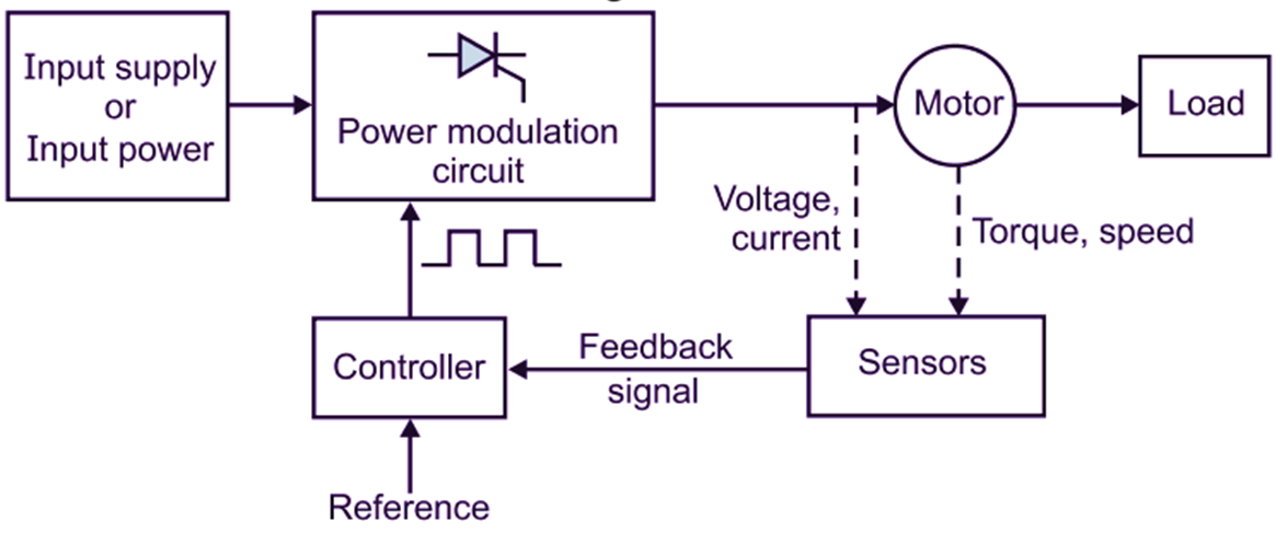
Fig. 2: General block diagram of electric drive
The input supply A.C. or D.C. is connected to motor through power modulation circuit. The input parameters of motor (voltage, current) and output parameters of motor (torque, speed) are sensed by appropriate sensors. Mechanical load is connected to the motor. The sensor data is given to the controller. A reference is set for maximum input current voltage and desired torque, speed etc. The input power to motor is fed through power modulation circuit. The voltage, current, speed, torque are sensed by respective sensors. The starting current is controlled by applying reduced voltage at start. The controller gives pulses and operates the power modulation circuit accordingly. The input voltage is also sensed simultaneously. A reference is set i.e. desired speed is set. The sensor senses the speed and torque and gives feedback signal. Based on feedback signal, the controller operates the power modulation circuit. The power modulation circuit modulates input power (or voltage) such that desired speed is reached.
Advantages of Electric Drives
Main advantages are :
- Reliability.
- Versatility of speed control.
- Speed control over a wide range.
- Smooth speed control.
- Optimization and automation have improved static and dynamic behaviour of these drives.
- Use of inverters using thyristors. Use of converters makes drives more reliable and accurate in operation.
- Steady-state and dynamic characteristics of electric drives can be shaped to satisfy load requirements.
- Electric drives have flexible control characteristics.
- Speed can be controlled easily.
- Speed can be controlled in wide range.
- Electric braking is possible.
- Starting, braking, speed control mechanisms are very simple and easy to be operated.
- Control characteristics can be made more flexible with the introduction of :
- Thyristors.
- Power transistors.
- IGBTs.
- ITOs.
- ICs linear/digital.
- Micro computers.
- As per the load requirements, it is possible to reshape the characteristics of drives in an optimum manner.
- Speed, torque and transitions from one mode to another can be controlled very smoothly and even steplessly.
- High dynamic performance, high efficiency can be obtained by implementing optimal control strategies.
- Automatic fault detection system can be provided to the drives.
- To provide automatic control operations in desired sequence can be obtained by the provision of logic controllers and computers.
- The speciality of electric motors are :
- High effciency.
- Small no-load losses.
- Considerable short time overload capability.
- Various designs can be provided to motor to make them compatible with different loads.
- If we compare such electric drives with other types of drives then :
- Electric drives have much more life,
- Maintenance required is much less.
- Noise production is less (and bearable).
- Operations are comparatively very clean.
- If you compare with other types of drive, then electric drives need no fuel, no flue gases, no air pollution.
- Started instantly and loaded to full-load conditions with less time.
- It can be operated in all four quadrants of speed-torque plane.
- Their operation is possible in all surroundings like explosive, radio-active environment, submerged in liquids, vertical/horizontal mounting conditions.
- Compared with other forms of braking, electric braking gives smooth deceleration, so increases life of components/equipments.
- Regenerative braking gives considerable savings in energy. This is not available in other systems.
- Conversion of electrical to mechanical energy and mechanical to electrical energy is done efficiently as well as economically.
Disadvantages of Electric Drive
- This drive needs electric supply. So if electric supply fails, it cannot be operated.
- Alternative arrangement of supplying electrical energy is needed to be supplied if operation is to be continued.
Parts (Components) of Electric Drive and Functions of Each Component
As shown in the block diagram of electric drive the major parts are: Load, motor power modulator, control unit and source.
(A) Load
Components of load torque :
- Frictional torque : Friction is present at motor shaft bearings and other various parts.
- Windage torque: When motor runs, wind generates and torque opposing the motion is known as windage torque.
- Torque required to do the useful mechanical work : The nature of this load torque depends on particular application. Torque is constant and independent of speed in case of low speed hoist. Load torque is the function of speed in :
- Fans.
- Compressors, centrifugal pumps, high speed hoists, ship-propellers, etc.
(B) Types of Motors
Commonly used motors as drives are already discussed earlier such as :
- D.C. motors – Shunt, series, compound, P.M. motor.
- A.C. motors – Squirrel cage, slip-ring, linear.
- Synchronous motors – Wound field, permanent/magnet.
- Brushless D.C. motors.
- Stepper motors.
- Switched reluctance motors.
Power Modulators
These can be grouped into three parts :
- Converters.
- Variable impedances.
- Switching circuits.
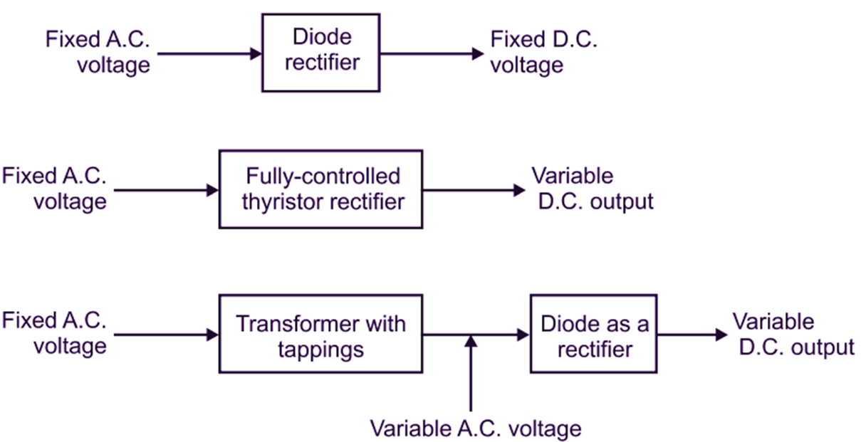
Converter: A. C. to D.C. converters
Variable impedance
Resistors, inductors, their combination with steps or continuous variations for lining the currents in the circuits are used
Switching circuits
These are used for :
- Changing the motor connections to change quadrant operations.
- For auto-starting / braking.
- Operation as per pre-determined sequence.
- Maloperation preventions (to provide interlocking).
- Disconnection in abnormal happenings.
High power electromagnetic relays are used in the functioning of switching operations.
Sources
- For small drives – 230 V, A.C„ single phase.
- For moderate and high power – 440 volts, 50 Hz, 3-phase A-C.
- For bulk capacity motors – 3.3 kV, 6.6 kV, 11 kV. Some drives are power from batteries, 6 V, 12 V, 24 V, 48 V and 11 V D.C.
Control unit
Control unit depends upon power modulator used. For semiconductor converters, control unit consists of firing circuit, employlng digital linear circuit and transistors, microprocessor.
Choice of Electric Drive
So many factors have to be considered for selecting a particular drive for particular work (load). Following are the major and important factors for choice of drive (Selection of drive).
1. Reliability of operation throughout the ranges of load.
2. Steady state operation requirements such as:
- Duty cycle.
- Speed range.
- Efficiency.
- Rating.
- Quadrants of operation.
- Speed regulation.
- Speed/torque characteristic nature.
- Fluctuations in speed.
3. Sources required such as:
- Magnitude of voltage.
- Type of voltage (A.C./D.C.) source.
- Voltage fluctuations.
- For A.C. source – Power factor.
- Harmonics.
- Harmonics affecting loads.
- Regenerated power acceptability.
4. Cost:
- Capital cost.
- Running cost.
- Maintenance cost.
- Service cost.
5. Life: More life expected.
6. Capacity:
- Thermal capacity.
- Service capacity.
- Rating.
- Peak torque capacity.
- Capacity to face environmental changes.
- To work satisfactory in types of location.
7. Restrictions:
- Space restrictions.
- Weight restrictions
8. Transient operation requirements:
- Values of acceleration.
- Values of deceleration.
- Starting performance.
- Braking performance.
- Reversing performance.
9. Energy losses and its cost.
10. Choice also depends on types of drives.
11. Power density and volume of motor.
12. Suitability in bad environments (Hazardous environments).
13. Matching with spare parts available in the market.
General Applications of Electric Drives
Important points to be noted regarding electric drives:
- Have flexible control characteristics.
- Range of torque, power, speed control – very wide.
- Can be started, stopped frequently.
- Wide variety ratings.
This supports wide ranges of applications such as:
- Rolling mills.
- Textile mills.
- Cranes.
- Paper mills.
- Marine drives.
- Refrigeration.
- Air-conditioning.
- Sugar factory.
- Production industries.
- Small, big workshops.