In this topic, you study 3 Point Starter (Three Point Starter) – Working, Diagram & Construction.
Fig. 1 shows this type of starter. Since this starter has three terminals L, A and F as illustrated in the figure, it is called a three-point starter. Terminal L is connected to the line, terminal A to the armature and terminal F to the field. Now, let us first see the construction of the starter.
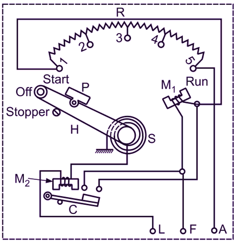
Fig. 1: Three-point starter for a dc shunt motor
Construction of Three-point starter
It consists of a starting resistor R sub-divided between number of contact studs (1 to 5). The starting handle (H) is pivoted on one side and its other side is free to move against a strong spring S and make contact with each stud and at the same time with the brass arc B, during the starting operation. The starter is also provided with two protective devices called no-volt release and over-load release. The no-volt release consists of an electromagnet M1 and a hinged soft iron piece P carried by the starting handle. The coil of this electromagnet has a large number of turns wound on a U-shaped iron core and it is connected in series with the field winding. The over-load release consists of another small electromagnet M2 and soft iron armature C. The coil of this electromagnet has few turns and it is connected in series with the motor. One end of the armature C is pivoted and its other side carries a link of some conducting material. The two brass studs facing this link are connected to the two ends of the coil of the electromagnet M1. Fig. 1 also illustrates the internal wiring of such a starter.
Operation of Three-point starter
To start the motor, the dc supply is first switched on. The starting handle is then slowly moved against the spring in the clockwise direction. When the handle makes connection with the first stud, the field winding of the motor gets connected directly across the line through the coil of the no-volt release and at the same time the entire starting resistor comes in series with the armature. As the handle is moved further, the starting resistor is gradually cut off from the armature circuit. Finally, when the handle reaches the running position (i.e. final stud), the starting resistor is completely cut off and the motor starts operating on full speed. Handle is held in this position against spring tension by the electromagnet M1 of no-volt release.
Functions of No-Volt Release
Following important functions are carried out by the no-volt release.
- When the handle is in the RUN (or ON) position, a small iron piece P on it is attracted by the electromagnet M1 of no-volt release energized by the field current flowing through its coil. Thus the handle is held in ON position against the pull of a spring. Because of this specific function which is carried out by the no-volt release, electromagnet M1 is called hold-up magnet and its coil is termed hold-on coil.
- If the supply fails, or is switched off, or if the field circuit is broken, the demagnetized electromagnet of the no-volt release no longer attracts the iron piece and a return spring brings the handle to OFF position. This prevents the starting of the motor without any starting resistance in its armature circuit when the supply is again restored.
- The pull of the electromagnet of the no-volt release also becomes insufficient under low-voltage condition and the handle returns to the OFF position, thus providing protection against low voltage. This is the reason why no-volt release is also sometimes called low-voltage release.
Function of Over-Load Release
Since the coil of the electromagnet M2 of the over-load release is connected in series with the motor, it always carries the line current. If the current exceeds certain predetermined value due to over-load (or some fault), the electromagnet M2 of the over-load release attracts the armature C which when lifted, bridges two brass studs connected to the two ends of the coil of the electromagnet M1 of the no-volt release. As soon as the coil of the electromagnet M1 of the no-volt release holding the starting handle in the RUN position is short circuited, it gets demagnetized. The spring then pulls the handle back to OFF position and thus disconnects the motor from the supply. The over-load release can be set for different values of the current by adjusting the position of its armature with the help of a set screw provided for this purpose.
A slightly modified form of a three-point starter as shown in Fig. 2 is also in use in which the brass arc (B) is eliminated and the field circuit is connected to the supply through the starting resistor. With this modification, it will be seen that when the starting handle is moved from first stud to the last stud, the portion of the starting resistor which is cut off from the armature circuit is included in the field circuit. But as the resistance of the starting resistor is very small as compared to that of shunt field circuit, the inclusion of starting resistor in the field circuit has very little effect on the field current.
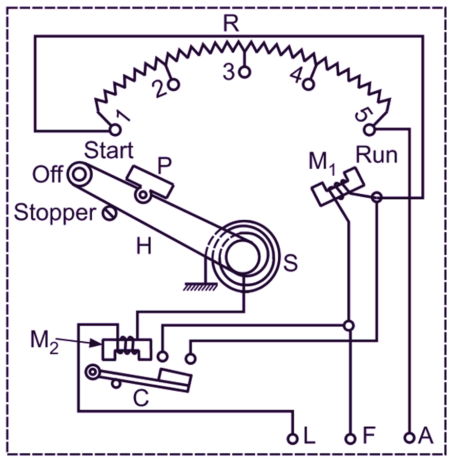
Fig. 2: Three-point starter, a modified form
Three-point starter is not suitable for the variable-speed motors using field control. Because in the case of such a motor, when the speed is increased by reducing the field current with the help of field regulator as,
\[\text{N}\propto \frac{\text{1}}{\phi }\propto \frac{\text{1}}{{{\text{I}}_{\text{sh}}}}\]
It causes weakening of the hold-up magnet. This weakening may be to such an extent that hold-up magnet fails to keep the starting handle in ON position and the motor is thus disconnected from the supply when it is not desired. This difficulty is overcome by using a four-point starter.