Anderson bridge is used to measure inductance in terms of a standard capacitance (C). This method is applicable for precise measurement of inductance over a wide range of values, from micro henry to several henries. The Fig. 1. shows the circuit diagram of the bridge. The circuit has the following components.
L1 = Inductance to be measured
R1 = Resistance of the inductor
r1 = Resistance connected in series with L1
r, R2, R3, R4 = Known non-inductive resistors
C = Fixed standard capacitor.
.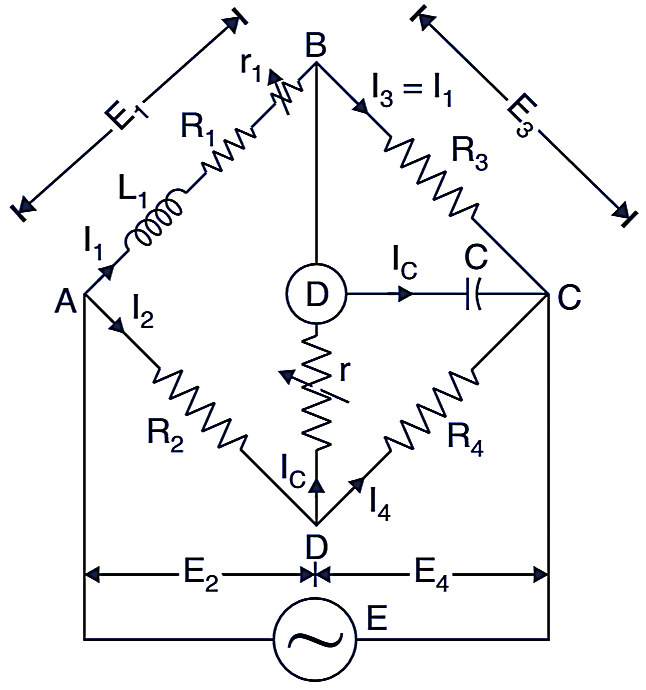
Fig. 1. Anderson bridge
Balance is obtained by varying (adjusting) the resistance r1 and r.
At balance,
\[{{\text{I}}_{\text{1}}}\text{ = }{{\text{I}}_{\text{3}}}\]
and
\[{{\text{I}}_{\text{C}}}\left( \text{r +}\frac{1}{\text{j}\omega \text{C}} \right)=\left( {{\text{I}}_{\text{2}}}-\text{ }{{\text{I}}_{\text{C}}} \right){{\text{R}}_{\text{4}}}\]
Now.
\[{{\text{I}}_{\text{1}}}{{\text{R}}_{\text{3}}}\text{ = }{{\text{I}}_{\text{C}}}\times \frac{1}{\text{j}\omega \text{C}}\]
i.e.
\[{{\text{I}}_{\text{C}}}\text{ = }{{\text{I}}_{\text{1}}}{{\text{R}}_{\text{3}}}\text{ j}\omega \text{C}\]
Writing balance equations
\[{{\text{I}}_{\text{1}}}\left( {{\text{R}}_{\text{1}}}\text{+ }{{\text{r}}_{\text{1}}}\text{+ j}\omega {{\text{L}}_{\text{1}}} \right)\text{ = }{{\text{I}}_{\text{2}}}{{\text{R}}_{\text{2}}}\text{+ }{{\text{I}}_{\text{C}}}\text{ r}…(i)\]
and
\[{{\text{I}}_{\text{C}}}\left( \text{r +}\frac{1}{\text{j}\omega \text{C}} \right)=\left( {{\text{I}}_{\text{2}}}-{{\text{I}}_{\text{C}}} \right){{\text{R}}_{\text{4}}}\]
Putting the value of IC the eq. (1) can be written as:
\[{{\text{I}}_{\text{C}}}\left( {{\text{R}}_{\text{1}}}\text{+ }{{\text{r}}_{\text{1}}}\text{+ j}\omega {{\text{L}}_{\text{1}}} \right)\text{ = }{{\text{I}}_{\text{2}}}{{\text{R}}_{\text{2}}}\text{+ }{{\text{I}}_{\text{C}}}\text{ r}\]
or,
\[{{\text{I}}_{\text{1}}}\left( {{\text{R}}_{\text{1}}}\text{+ }{{\text{r}}_{\text{1}}}\text{+ j}\omega {{\text{L}}_{\text{1}}}-{{\text{R}}_{\text{3}}}\text{ j}\omega \text{C r} \right)\text{ = }{{\text{I}}_{\text{2}}}{{\text{R}}_{\text{2}}}…(iii)\]
Now putting the value of IC the eq. (ii) can be written as:
\[{{\text{I}}_{\text{1}}}{{\text{R}}_{\text{3}}}\text{ j}\omega \text{C}\left( \text{r +}\frac{1}{\text{j}\omega \text{C}} \right)=\left( {{\text{I}}_{\text{2}}}-\text{ }{{\text{I}}_{\text{1}}}{{\text{R}}_{\text{3}}}\text{ j}\omega \text{C} \right){{\text{R}}_{\text{4}}}\]
or,
\[{{\text{I}}_{\text{1}}}\left( \text{j}\omega \text{C }{{\text{R}}_{\text{3}}}\text{ r}+\text{j}\omega \text{C }{{\text{R}}_{\text{3}}}{{\text{R}}_{\text{4}}}\text{+ }{{\text{R}}_{\text{3}}} \right)\text{ = }{{\text{I}}_{\text{2}}}{{\text{R}}_{\text{4}}}…(iv)\]
From eq. (iii) and (iv) we get
${{\text{I}}_{\text{1}}}\left( {{\text{R}}_{\text{1}}}\text{+ }{{\text{r}}_{\text{1}}}\text{+ j}\omega {{\text{L}}_{\text{1}}}-{{\text{R}}_{\text{3}}}\text{ j}\omega \text{C r} \right)\text{ }$
\[\text{= }\left[ \frac{{{\text{R}}_{\text{2}}}{{\text{R}}_{\text{3}}}}{{{\text{R}}_{\text{4}}}}+\frac{\text{j}\omega \text{C }{{\text{R}}_{\text{2}}}{{\text{R}}_{\text{3}}}\text{ r}}{{{\text{R}}_{\text{4}}}}+\text{j}\omega \text{C }{{\text{R}}_{\text{2}}}{{\text{R}}_{\text{3}}} \right]\]
Equating real and imaginary tenus,
\[{{\text{R}}_{\text{1}}}\text{ = }\frac{{{\text{R}}_{\text{2}}}{{\text{R}}_{\text{3}}}}{{{\text{R}}_{\text{4}}}}\]
.\[{{\text{L}}_{\text{1}}}\text{ = C}\frac{{{\text{R}}_{\text{3}}}}{{{\text{R}}_{\text{4}}}}\left[ \text{r}\left( {{\text{R}}_{\text{4}}}\text{+ }{{\text{R}}_{\text{2}}} \right)+{{\text{R}}_{\text{2}}}{{\text{R}}_{\text{4}}} \right]\]
Advantages of Anderson Bridge
- The adjustments are carried out by manipulating R1 and r and they become independent of each other. This is a superior point. It is easy to obtain balance in this bridge as compared to Maxwell Bridge.
- A fixed capacitor can be used instead of a variable capacitor.
- This bridge may also be used to measure capacitance in terms of inductance.
Disadvantages of Anderson Bridge
- The Anderson’s bridge is very complex as compared to Maxwell Bridge. It has a circuit with more components. The balance equations are also very tedious.
- Due to above reason, Maxwell bridge is preferred.