In this topic, you study Construction of Transformer.
A transformer mainly consists of the following; Magnetic Circuit, Electrical Circuit & Dielectric Circuit.
Magnetic Circuit
It provides the path for magnetic flux and consists of limbs, yokes and clamping structures.
Electrical Circuit
It basically provides the path for electric current. In a transformer, it consists of primary and secondary windings.
Dielectric Circuit
It consists of insulation in different forms used at different places in a transformer (e.g. between the core and low-voltage winding, between the low voltage and high voltage winding, etc.).
A transformer mainly consists of core and coils (windings). With the increase in the size (capacity) and operating voltage, it also needs other parts such as suitable tank, bushings, conservator, breather, explosion vent, Buchholz relay, etc. (Fig. 1). Various parts of the transformer are briefly described below.
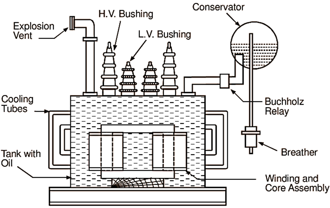
Fig. 1: Schematic representation of a large capacity single phase transformer
Laminated Steel Core
Basically, the core made up of magnetic material is used to provide the path of low reluctance (opposition) for the flux. Lesser the reluctance of the magnetic circuit, stronger is the field. The material actually used for the core is high grade silicon steel in the form of laminations about 0.35 to 0.5 mm thick. These laminations are varnished or coated with enamel to insulate them from each other. The core is assembled in such a fashion that it provides continuous magnetic circuit with a minimum air gap. For this, the joints in the adjacent layers are staggered. Fig. 2 (a) illustrates the arrangement of joints in two adjacent layers of L-shaped laminations and Fig. 2 (b) of I-shaped laminations.

(a)

(b)
Fig. 2: Arrangement of joints in the adjacent layers of laminations
For small transformers, the cross-section of the limb of the core can be rectangular (Fig. 3 a), as the coils wound on it can also be rectangular. But as the size of the transformer increases, it becomes wasteful to employ rectangular coils and circular coils are usually preferred. Therefore, under such condition, square or stepped (Figs. 3 b, c, d) cross sections are used for the limbs. More the number of steps, more circular is the section and lesser is the copper required for the coils wound over it. This is because the circular section has the smallest perimeter for a given area. However, the saving thus effected due to core stepping must be balanced against the increased labour charges to construct such cores.
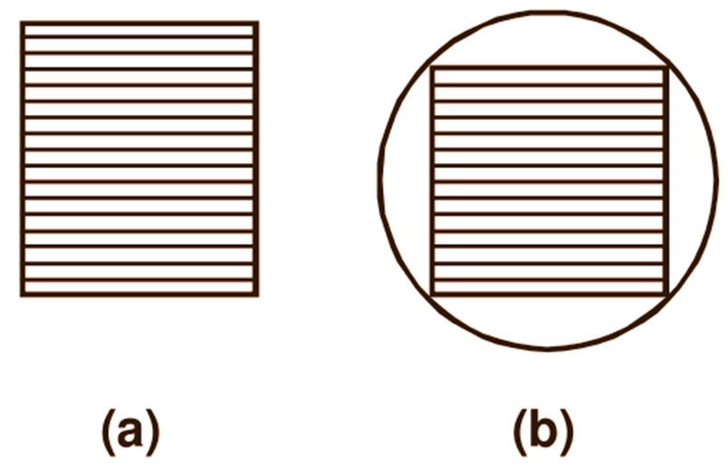
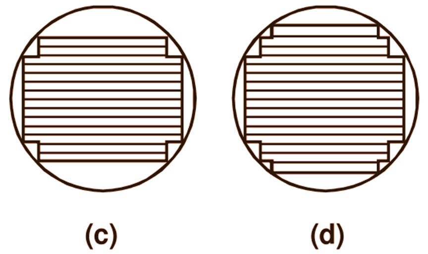
Fig. 3: Different cross-sections for the transformer limbs (a) Rectangular, (b) Square, (c) 2-stepped or cruciform, (d) 3-stepped
The laminated construction and the choice of silicon steel as magnetic material for the core help in reducing the iron loss of the transformer.
Windings
The coils forming the primary and the secondary windings are former wound using well insulated copper conductor in the form of round wire or strip. These coils are then placed around the limbs of the core. The windings are insulated from each other and the core using cylinders of insulating material such as press board or bakelite. In the elementary transformer illustrated in Fig. 4, the primary and secondary windings are shown on separate limbs of the core for simplicity.
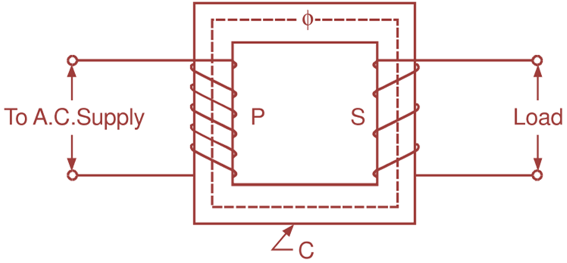
Fig. 4: Elementary transformer
However, if such an arrangement is used in actual practice, all the flux produced by the primary winding will not link with the secondary winding as some of the flux will leak out through air. Such flux is known as leakage flux. More the value of the leakage flux, poorer is the performance of the transformer. Therefore, to reduce this leakage flux, the primary winding and the secondary winding are placed together on the same limb in actual transformer. These windings are either cylindrical in form and concentric or sandwich type as illustrated in Fig. 5.
(a)
(b)
Fig. 5: Transformer windings (a) Cylindrical in form and concentric, (b) Sandwich type
While placing the cylindrical coils concentrically around the particular limb, the one which is designed for low voltage is placed near the core and the other which is designed for high voltage is placed after that. This is because, it is always easy to insulate the low voltage winding with respect to the core. In sandwich type, the windings are divided into number of small coils and these coils of high voltage (H.V.) and low-voltage (L.V.) windings are interleaved. The top and bottom coils which are near the core are of low-voltage winding only.
Transformer Tank
Except in small sizes, the whole transformer assembly is placed in a fabricated sheet metal tank and immersed in the oil which serves both the purposes of providing insulation and cooling. The heat generated in the windings and the core is carried by the oil to the external surface of the tank. Cooling tubes are provided to increase the surface area of the tank for more effective cooling.
Terminal Bushings
The leads of the transformer brought out from the tank are insulated from it with the help of porcelain bushings. These bushings are fitted to the tank.
Conservator
In a transformer, provision of some space above the oil level is always essential to take up the expansion and contraction of the oil with changes of temperature in service. When transformer becomes warm, the oil expands and the air at the top of the oil is expelled. When the transformer cools, oil contracts and outside air is drawn into the transformer. This process is known as breathing of the transformer. Unless proper precautions are taken, the outside air which enters the transformer during this process can have considerable moisture. When the oil in the transformer is exposed to such moist air, it readily absorbs the moisture from the air and loses its insulating value to some extent. This deterioration of oil can be prevented by using a conservator. The conservator is an airtight cylindrical metal drum supported on the transformer tank. This drum is connected by pipe to the transformer tank and is always partly filled with oil. The expansion and contraction of the oil in the main tank with the changes of temperature is now taken up by the conservator. With this arrangement, since the main tank remains always full with oil, the surface of the oil is not directly exposed to air.
Breather
The displacement of air above the oil level in the conservator during the breathing process of the transformer takes place through the apparatus known as a brearher. It contains a drying agent, such as calcium chloride or silica gel, which extracts the moisture from the air. The breather also cleans the air by removing the dust particles present in it. Thus, only dry and clean air is allowed to come in contact with the oil in the transformer.
Buchholz Relay
It is a type of protective device mounted in the pipeline connecting the main tank to the conservator. Due to excessive heat developed during the fault condition, the oil in the tank in the vicinity of the fault point gets decomposed and different types of the gases are liberated. These gases operate the Buchholz relay which in the initial condition gives alarm to the operator. If the fault developed is converted into a serious type of fault, then this relay trips off the main circuit breaker.
Explosion Vent
The bent up pipe fitted on the upper surface of the tank is known as explosion vent or relief valve. It is provided with a diaphragm made out of glass sheet, aluminium foil or a bakelite sheet. In the event of the fault condition, if the excessive pressure is developed inside the tank due to liberated gases, the diaphragm in the explosion vent bursts and releases the pressure, thus avoiding damage to the transformer.