Before we go into the circuit details of CSI we must know the difference between a VSI and a CSI. The voltage and current sources are as shown in Figs .1(a) and (b) respectively.
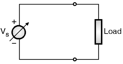
(a) Voltage source
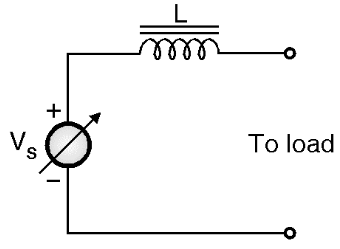
(b) Current source
Fig.1: Different types of sources.
The current source is derived from the voltage source by connecting a large value inductance in series with the voltage source as shown in Fig. 1(b). The important points to be remembered about a current source are:
- It supplies a constant output current (due to the presence of the series connected inductance L). If the output current is to be varied then we have to vary the source voltage.
- The load current waveform will be fixed but the load voltage waveform will be determined by the nature of load.
- The output impedance of a current source is very high ideally ∞.
Principle of Operation of Current Source Inverter (CSI)
The circuit diagram of current source inverter is shown in Fig. 2.
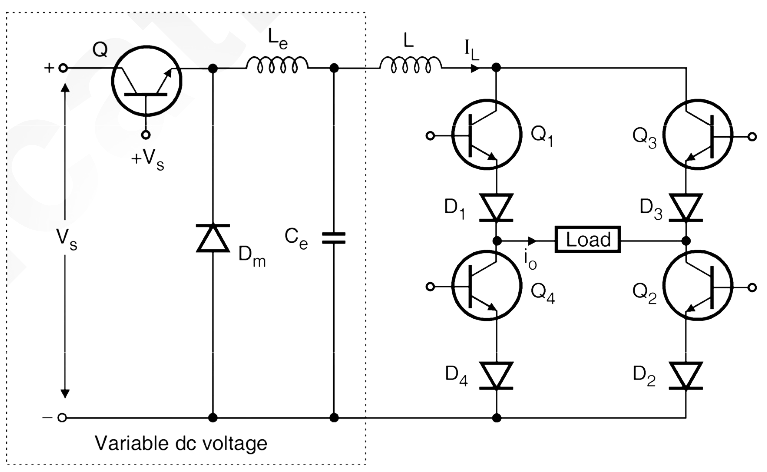
Fig. 2: CSI using transistor
The variable dc voltage source is converted into a variable current source by using inductance L. The current IL supplied to the single phase transistorised inverter is adjusted by the combination of variable dc voltage and inductance L. The waveforms of gate currents and output current i0 are as shown in Fig. 3. When transistors Q1 and Q2 conduct simultaneously, the output current is positive and equal to + IL. When transistors Q3 and Q4 conduct simultaneously the output current i0 = – IL. But i0 = 0 when the transistors from same arm i.e. Q1 Q4 or Q2 Q3 conduct simultaneously.
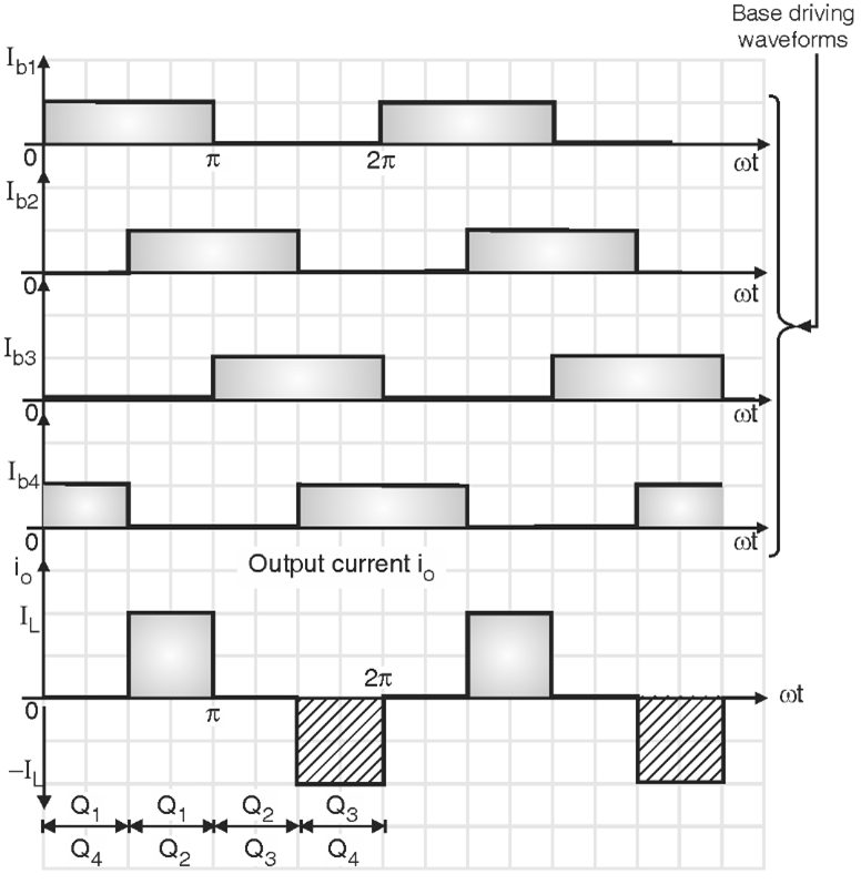
Fig. 3: Waveforms for single phase current source inverter.
The output current waveform of Fig. 3 is a quasi-square waveform. But it is possible to obtain a square wave load current by changing the pattern of gate driving signals. Such waveforms are shown in Fig. 4. The load current waveform in CSI has a defined shape, as it is a square waveform in this case.
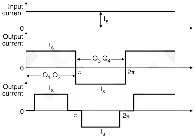
Fig. 4: Waveforms
But the load voltage waveform will be dependent entirely on the nature of the load. The load voltage with the resistive load will be a square wave, whereas with a highly inductive load it will be a triangular waveform. The load voltage will contain frequency components at the inverter frequency f, equal to 1 / T and other components at multiples of inverter frequency. The load voltage waveforms for different types of loads are shown in Fig. 5.
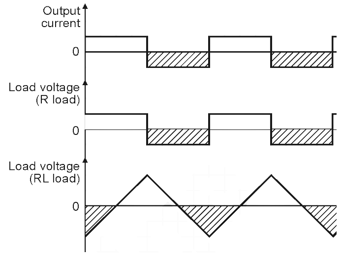
Fig. 5: Load voltage waveforms for different types of loads (current source inverter).
Advantages of Current Source Inverter (CSI)
- As the input dc current is controlled, the misfiring or short circuiting of the devices connected in CSI will not be a serious problem.
- The peak current flowing through the switching devices (transistors, thyristors etc.) is limited to a safe value.
- The commutation circuits required for thyristors are simpler.
- The CSI has an inherent ability to handle the reactive or regenerative loads.
Drawbacks of Current Source Inverter (CSI)
- It requires a large reactor (L).
- CSI needs an extra converter stage as a variable voltage source.
- The dynamic response of CSI is slower than that of a VSI.