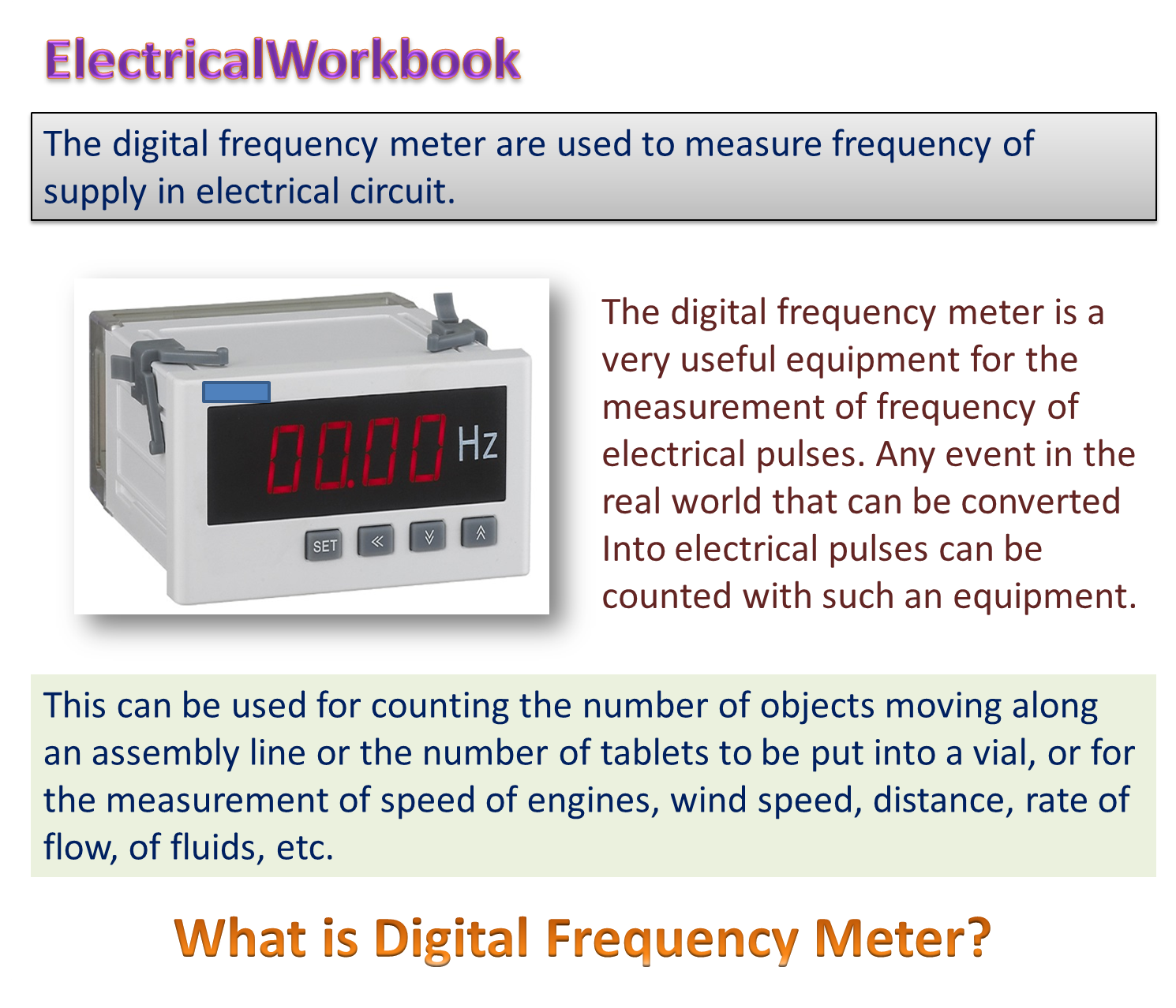
Working Principle of Digital Frequency Meter
In digital frequency meter, the unknown frequency signal is first converted into a train of pulses and then continuously supplied to one of the two inputs of the AND gate.
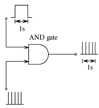
Figure (1): Basic Principle digital frequency meter.
A pulse having 1’s duration is applied to another input terminal of the gate is shown in figure (1). The total number of pulses passed through the gate during this time period is counted by an electronic counter. Here each pulse (in a train of pulses) indicates one cycle of the unknown signal. Therefore, total number of pulses counted by the counter is directly proportional to the frequency of the applied unknown signal.
Block Diagram and Working of Digital Frequency Meter
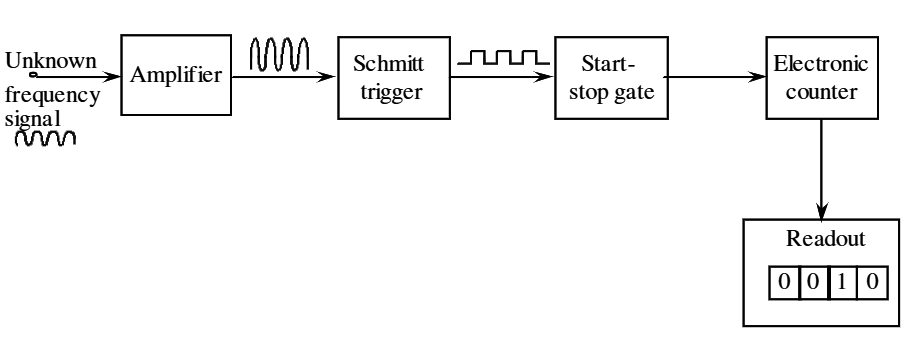
Figure (2): Basic Block Arrangement of Digital Frequency Meter
The block diagram of digital frequency meter is shown in figure (2). The unknown frequency signal is applied to the amplifier, where the signal is strengthened or amplified to a suitable level, and then applied to input of Schmitt trigger circuit. The function of the Schmitt trigger is to change the amplified input signal into square wave signal with fast rise and fall times. This converted square wave is properly differentiated and then clipped (by means of differentiator and clipper circuits). Thus a train of pulses appears at the output of Schmitt trigger and each pulse represents one single (1’s) cycle of the input signal. These train of pulses are then applied to the start/stop gate. When the start/stop gate is enabled or opened, the input pulses are allowed to pass through it and appears at the input of the counter. Then, the counter begins to count the pulses.
When the start/stop gate is disabled or closed, the pulses are not allowed to pass to the counter and then the counter stops counting. During the time period of enabling and disabling the gate, the pulses are counted arid the count is displayed on the digital readout (display unit). The measurement of this time period gives the value of unknown frequency signal. Then the value of unknown frequency is calculated by using the formula,
\[f=\frac{N}{t}\]
Let,
f – Unknown frequency of the applied signal.
t – The time period between enabling and disabling of the gate.
N – Total number of counts displayed.