In this topic, you study Electrical Isolator – Definition, Working, Diagram, Function, Advantages & Types.
Electrical Isolator is disconnecting switch which operate under no load condition. It does not have any current breaking or making capacity. Electrical Isolator also known as Disconnector or Disconnect switch or electrical isolator switch.
Isolator Function
Isolators cannot be used for breaking load currents. Isolators are used in addition to circuit breakers while opening a circuit, the circuit breaker is opened first then isolator. While closing a circuit, the isolator is closed first, then the circuit breaker. Isolators are necessary on supply side of circuit breakers in order to ensure isolation of circuit breakers from live parts for the purpose of maintenance. Isolators used in power-systems are generally 3-pole isolator. The 3-pole isolator has three identical poles. Each pole consists of two or three insulator posts mounted on a fabricate support. The conducting parts are supported on the insulator post. The conducting parts consist of conducting copper or aluminium rod fixed and moving contacts. During the opening operation the conducting rod swine apart and isolation is obtained
The simultaneous operation of 3-poles is obtained by mechanical interlocking of three poles. For all the three poles, there is a common operating mechanism. The mechanism may be manual electrical motor mechanism and Pneumatic mechanism. Further the isolator can be provided with earthing switching when required.
Types of Isolator
The following are the different types of isolator
- Vertical break type.
- Horizontal break type.
- Vertical pantograph type.
Vertical Break Isolator
Figure 2 shows the single pole isolator. The operating blade is hinged at one end so that making and breaking contact can be made. The operating blade do not twist because of adopting reverse loop contacts. For this reason, inspection and maintenance are almost unnecessary and sure operation is obtained with small operating torque. These units are tested for continuous current carrying capacity, short time current capacity and dry and wet flashover. The main advantage of such types of isolators is that they are simple in construction.
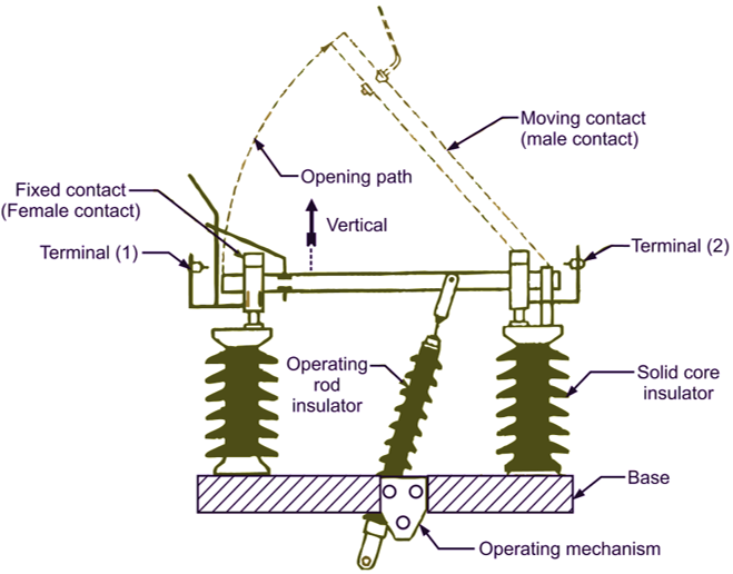
Fig. 2. Vertical break isolator.
Horizontal Break Isolator
In horizontal break rotating double break isolator, there are three insulator stacks per pole in which the two on each side is fixed and one at the centre in rotating type. The central insulator stacks can swing about its vertical axis through 90°. The fixed contacts are provided on top of each of the insulator stacks on the side. Moreover, the contacts bar is fixed horizontally on the central insulator stack. When the circuit fact shaft connects the two fixed contacts. When the circuit is open the central stack rotates through 90° and the contact shaft swings horizontally giving a double break. The three poles are interlocked by means of steel shaft.
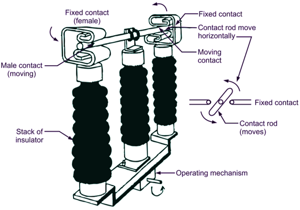
Fig. 2. Horizontal break isolator.
Pantograph Isolator
On closing, the linkages of pantograph are brought near by rotating the insulator column. In closed position the upper two arms of the pantagraph close on the overload station busbar giving a grip. The current is carried by the upper busbar to the lower busbar through the pantograph. During opening, the rotating insulator column is rotated about its axis and isolation is obtained between the line terminal and pantograph upper terminal. The main advantages of a pantograph isolator is that it covers less floor area.
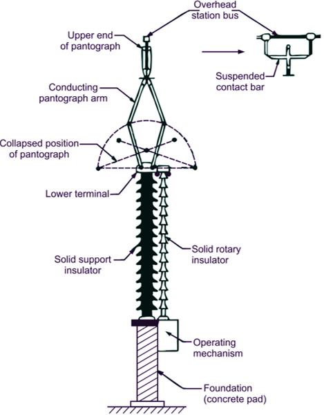
Fig. 3. Pantograph isolator.