In this topic, you study Power Transformer.
They are used in the generating stations and substations at each end of a transmission line. The transformers used at the generating station end of the transmission line are for stepping up the voltage and the transformers used at substation end of the transmission line are for stepping down the voltage. Based on the demand for power, these transformers are put into operation during the load periods and switched off during the light-load periods.
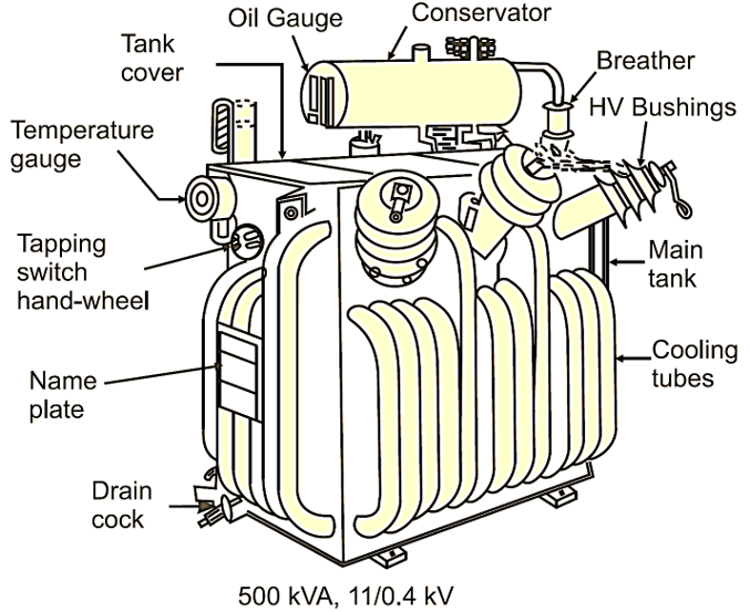
Fig. 1: Power Transformer
Description of Power Transformer given below in tabular form
| Particulars | Power Transformers |
| Connections
|
Delta/Delta or Delta/Star. Used for three-phase, 3-wire system. |
| Capacity | Commonly used range : 250 kVA to 10 MVA |
| Efficiency | Generally operated on full load. Hence, designed for maximum efficiency at or near full load |
| Flux density | 1.5 to 1.7 T |
| Ratio of iron loss to copper loss | 1 : 1 |
| Voltage regulation
|
6 |
| Cooling | Forced air cooled, forced oil cooled, forced water cooled, self oil cooled. |
Criteria for the Selection of Power Transformers
The main governing features for the purpose of selection of outdoor type, three phase, double-wound power transformers having ratings above 1600 kVA are, in brief, as follows.
Ratings: This includes kVA rating, nominal system voltage, no-load voltage ratio and frequency. The kVA rating shall be selected from the specified standard ratings as per the requirements. The secondary no-load voltage should be specified 5
Taps: On-load tap changers (OLTCs) on HV side may be specified wherever system conditions warant. In case of OLTC, the total number of taps should be 16 in steps of 1.25
Connection Symbol: The preferred connections for the transformers upto 66 kV (HV side ratings) are delta/star (Dyn) and star/star (YNyn). For higher voltages, connections star/star (YNyn) or star/delta (YNd) may be preferred. The selection of connection group should be made taking into consideration the requirements of parallel operation with other transformers.
Impedance: The transformer impedance is decided taking into consideration the secondary fault levels and the voltage dip.
Termination Arrangement: Primary and secondary terminals may be bare bushings, cable boxes or bus trunking depending upon the method of installation. For transformers upto 33 kV, porcelain bushings and for transformers of 66 kV and above, oil-filled, condenser-type bushings should be specified.
Cooling: The type of cooling may be ONAN, ONAN/ONAF, ONAN/ONAF/OFOF or OFWF depending upon kVA/MVA rating and voltage class (in kV).
Fittings and Accessories: Fittings and accessories should mainly include the following :
Magnetic oil level gauge with low level alarm contacts, winding temperature indicator with electrical contacts for alarm/trip, controlling fans and pumps, gas and oil actuated relay with alarm and trip contacts, explosion vent, oil temperature indicator with alarm and trip contacts, two oil sampling valves at top and bottom of the main tank.