In this topic, you study Welding Transformer – Theory, Types & Diagram.
AC welding sets supplying power for arc welding consist mainly of welding transformers. The welding transformer reduces the voltage from that of the supply down to about 70 V to 100 V which is the value needed for initiating the arc. In arc welding, an arc is struck between an electrode and the work-piece such that the joint is brought to fusion temperature by the heat of the arc (about 3500°C).
Drooping Characteristic of the Voltage Source
With ac supply, even though the open-circuit voltage necessary to strike the arc is between 70 V to 100 V, the voltage to maintain the arc depends on the type of electrode and the current used. It generally lies between about 20 V to 30 V. The most important feature of the arc is its negative resistance characteristic. The resistance of the arc decreases as the current increases. Hence, any slight increase in the current causes a decrease in the arc which in turn, increases the current further. This makes the maintenance of a steady arc impossible. The supply voltage must therefore be such that it should fall of rapidly as the current rises, thus counteracting the rise in current. The voltage source must therefore have a drooping characteristic as illustrated in Fig. 1. This drooping characteristic helps in maintaining the welding current substantially constant in the operating range irrespective of small variations in the arc length and consequent slight changes in the arc voltage, which are unavoidable in the manual arc welding. A fairly steady current during welding is essential for obtaining consistently good quality weld.
In ac welding set, the drooping characteristic can be achieved either by using the transformer in conjunction with a reactor connected in series with its secondary winding or by special design of the transformer itself. In both these cases, current control giving family of such drooping characteristics is achieved in many different ways. All these methods are basically based on changing the reactance of the welding circuit. Only few of them are briefly discussed below.
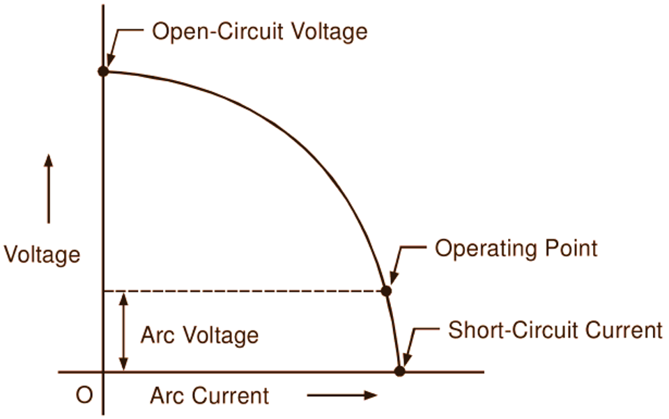
Fig. 1: Drooping characteristic of the voltage source.
Welding Transformers Combined with Reactors
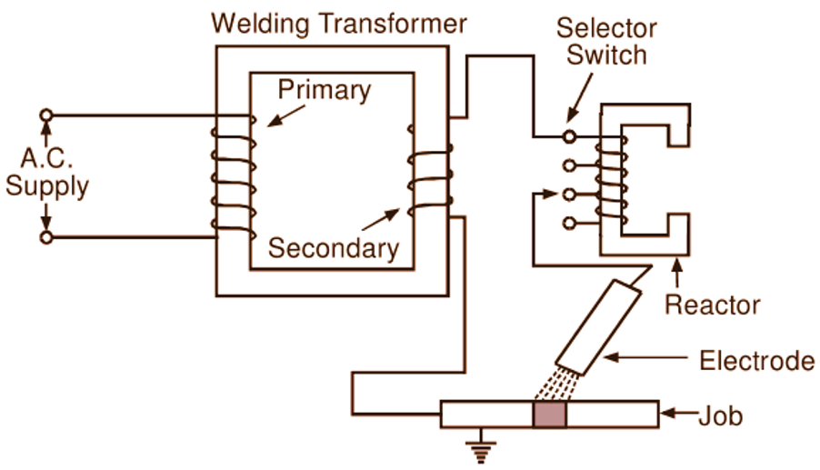
For controlling the welding current, a tapped reactor may be used in conjunction with a transformer as illustrated in Fig. 2 (a). More the number of turns of the reactor in the circuit, the higher is its reactance and the lower is the current. The air-gap in the reactor core may also be varied by mechanical means to change the reactance. Alternatively, reactance of the reactor may be changed by providing
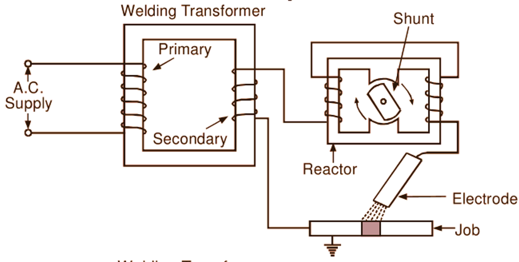
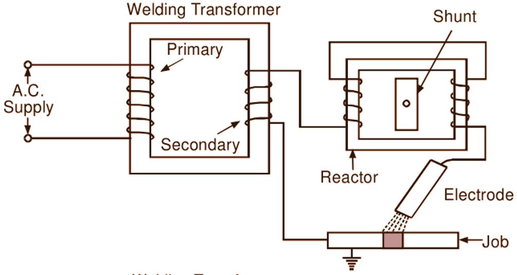
magnetic shunt in the core of the reactor. The number of designs are possible for gradual variation of the reactance of the reactor using such a magnetic shunt. This magnetic shunt may be in the form of an armature (Fig. 2 b), the angular position of which determines the reactance of the reactor. The reactance of the reactor is maximum (hence, minimum is the current) when the shunt circuit is almost closed except for the small air-gaps between rotatable and stationary core parts, and is minimum (hence, current is maximum) when rotatable core section turns through 90o. In between these two positions, any intermediate reactance can also be obtained. In another arrangement (Fig. 2 c), a movable (moving in the direction perpendicular to the plane of the paper) core is attached to a screw
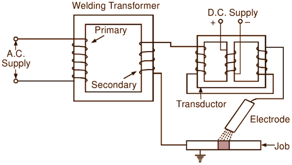
with which it can be inserted in the reactor core or taken out of the reactor core. When the movable core is completely out of the reactor core, reactance of the reactor is minimum and current under this condition is maximum. On the other hand, when the movable core is completely in the reactor core, the reactance of the reactor is maximum and the current is minimum. In some cases, the effect of variable reactance is obtained with the use of a dc controlled transductor (also called the saturable reactor) by varying its dc control current (Fig. 2 d). Saturation of the core to a greater or less extent is dependent on the strength of the direct current which in turn changes the reactance of a transductor.
(a)
(b)
(c)
(d)
Fig. 2: Welding transformer combined with (a) tapped reactor, (b) reactor having rotatable magnetic shunt, (c) reactor having movable magnetic shunt, (d) transductor
Variable Leakage Reactance Type Welding Transformer
The leakage reactance of the transformer itself can be varied by using different methods and thus it is possible to control the welding current without the aid of a separate reactor.
(a)
(b)
(c)
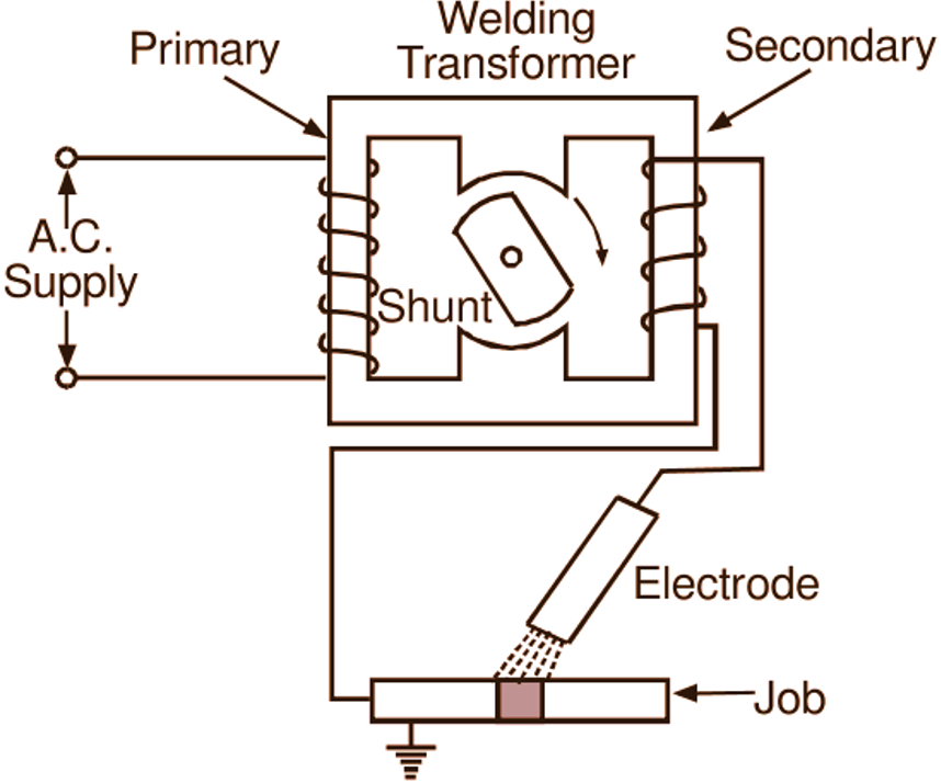
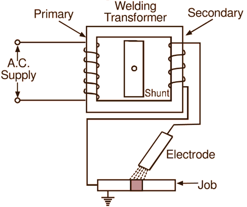
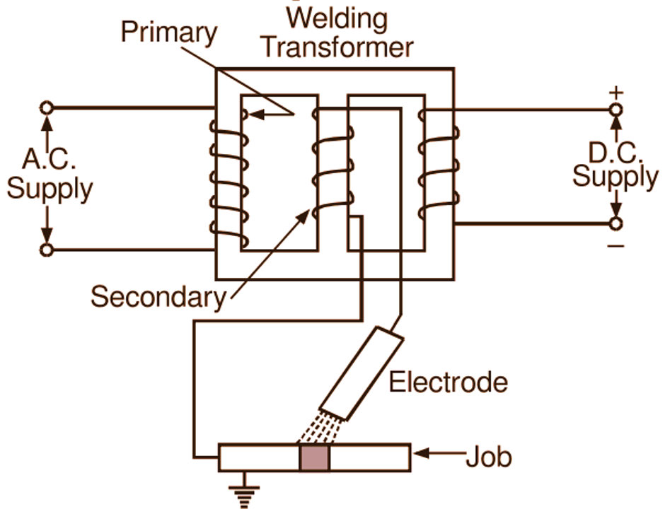
Fig.3: Variable leakage reactance type welding transformer with (a) rotatable magnetic shunt, (b) movable magnetic shunt, (c) provision for dc saturation of magnetic shunt.
Three such methods illustrated diagrammatically in Figs. 3 (a), (b) and (c) are similar in principle to those discussed earlier for changing the reactance of reactors used in conjunction with transformers. In the first method (Fig. 3 a), the leakage reactance of the transformer is changed with the help of a rotatable magnetic shunt whereas in the second method (Fig. 3 b), it is changed with the help of a movable magnetic shunt. In the third method (Fig. 3 c), the same thing is achieved by changing the saturation of the magnetic circuit with dc current. In some cases, moving coils may be used on the transformer leg to vary the leakage reactance which is determined by the relative positions of primary and secondary windings.