A mechanical tachometer is a device used to measure the rotational speed of a shaft or disk. It operates using mechanical components, typically gears, springs, and centrifugal force.
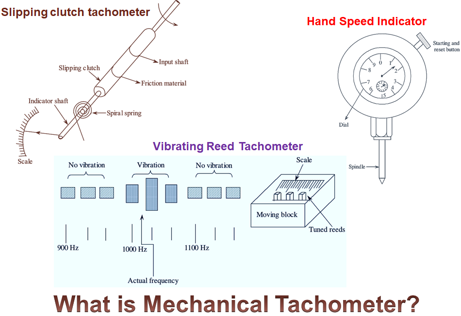
Mechanical Tachometer uses mechanical parts in their construction. Therefore, the speed is measured with the help of movement in the mechanical parts of the tachometer.
Types of Mechanical Tachometer
This type of tachometers are classified into different types. They are,
- Hand speed indicator
- Slipping clutch tachometer
- Vibrating reed tachometer
- Centrifugal force tachometer.
Hand Speed Indicator
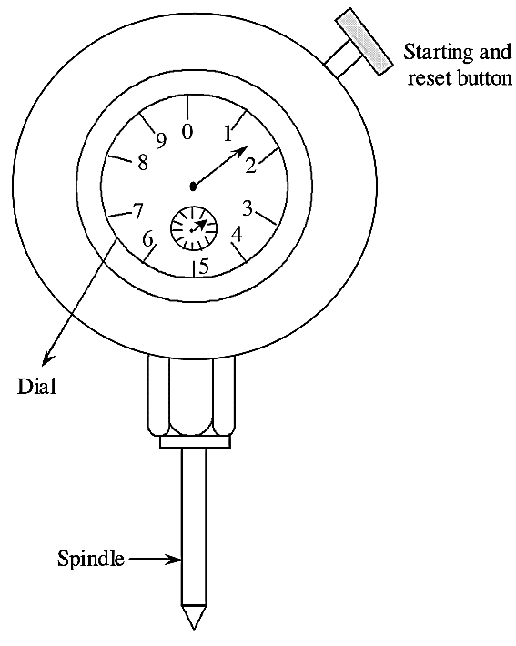
Figure 1: Hand speed indicator.
Figure (1) shows the hand speed indicator type tachometer. A stop watch and automatic disconnect counter is present in the hand speed indicator tachometer. Spindle, starting and reset button is shown in figure (1). The spindle of the hand speed indicator operates when it is connected to the shaft. The function of the automatic disconnect counter depends on starting and reset button. The watch is started and the automatic clutch is engaged, if the start button of the hand speed indicator is pressed. The automatic disconnect counter gets disengaged after 3 or 6 seconds. The average speed is indicated by this device. With the help of dial shown in figure (1), the rotational speed is indicated in terms of revolution per minute. This type of tachometers are used for the measurement of rotational speed from 20, 000 to 30,000 r.p.m. It’s accuracy is 1% of full scale.
Vibrating Reed Tachometer
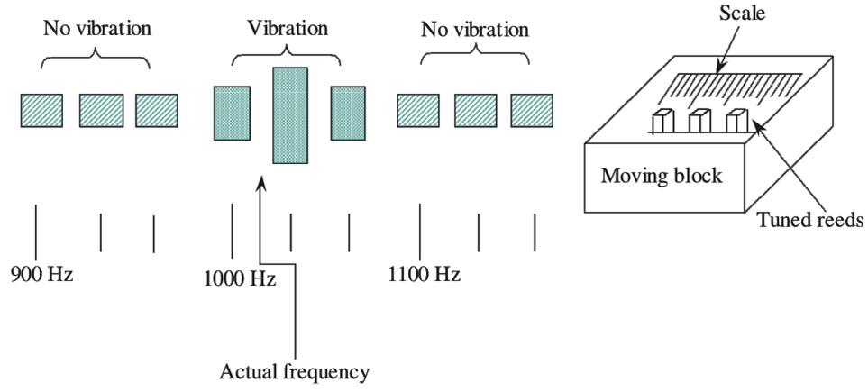
Figure 2: Vibration reed tachometer.
The basic principle behind this type of tachometer is vibration, speed of a body are related. From figure (2) it is noted that. it has a set of reeds which are arranged vertically and the natural frequency of vibration of each reed is indicated. These vertical reeds are arranged according to their natural frequency ranges. One end of the mounting block is sealed by the tuned reeds and the other end is free to vibrate. The tachometer mounting block, is attached on the machine frame whose shaft’s rotational velocity (rotational speed) is to be determined. Then the reed which is at resonance with the vibration of machine will vibrate most and vibration of all other reeds is very low and cannot be observed. Here the most frequently responding reed is identified and its vibration frequency is noted. This measured vibration frequency gives the measurement of shaft speed. This type of tachometers are not connected to the shaft to measure speed. This type of tachometers are widely used for the measurement of shaft speed in the range of 600 to 104 r.p.m. It’s accuracy is about ± 0.5% of full scale. These tachometers are frequently used for general monitoring.
Slipping clutch tachometer
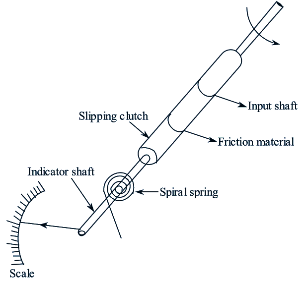
Figure 3: Vibrating Reed Tachometer.
The speed of the rotating shaft is measured by using this tachometer. Figure (3) shows the slipping clutch tachometer. The friction material is placed between slipping clutch and input shaft. The spiral spring is placed between slipping clutch and indicator shaft. The speed of the rotating shaft is indicated by the pointer which is placed on the indicator shaft. In this type of tachometers, the indicating shaft is driven by the rotating shaft through a slip clutch and hence, named as slipping clutch tachometer. The speed of the rotating shaft is indicated by the pointer which is connected to the indicator shaft. Therefore, the shaft speed is indicated by the pointer position of the tachometer.
Advantages of Mechanical Tachometers
- Simple Design: Easy to construct and use due to its straightforward mechanical operation.
- No Power Supply Required: Does not require an external power source, making it suitable for remote or low-power applications.
- Durable: Often more robust than electronic counterparts, withstanding harsh environments like high temperatures and vibrations.
- Cost-Effective: Lower initial cost compared to digital or electronic tachometers.
- Immediate Readout: Provides real-time measurements without needing complex calibration.
Disadvantages of Mechanical Tachometers
- Limited Accuracy: Less precise compared to digital tachometers.
- Wear and Tear: Mechanical components are prone to wear over time, requiring maintenance or replacement.
- Limited Measurement Range: May not be suitable for very high-speed or low-speed measurements.
- Bulkiness: Larger and heavier than electronic alternatives, making portability a challenge.
- No Data Logging: Cannot store or process data for future analysis.
Applications of Mechanical Tachometers
- Automotive Industry: Measuring engine speed (RPM) in vehicles.
- Industrial Machinery: Monitoring the speed of rotating equipment like turbines, pumps, and compressors.
- Marine Engineering: Used in ships to measure the speed of propeller shafts.
- Textile Industry: Monitoring the speed of spinning and weaving machinery.
- Laboratory Testing: Useful in experiments involving rotational speed measurement.