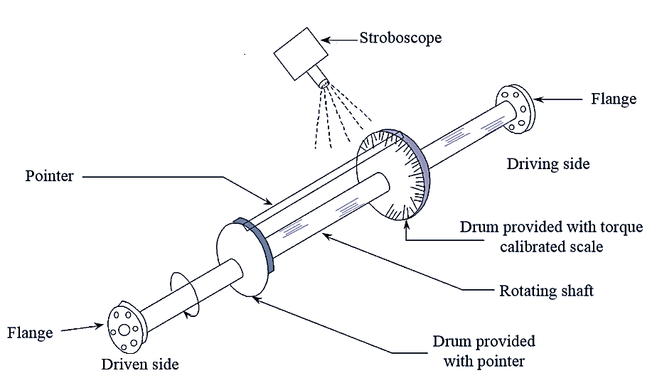
Figure 1: Mechanical Torsion Meter.
Mechanical torsion meter contains a shaft mounted between two drums and two flanges. One drum is provided with a torque calibrated scale and the other has a pointer (see Figure 1). A stroboscopic light source is used to note down the readings on the rotating shaft. One of the two ends of the rotating shaft is mounted on the driving engine whereas the other end is attached to the driven load. The angular displacement (angular twist) of the shaft over a fixed length is proportional to the torque exerted on the shaft. This angle of shift gives the amount of torque applied and is indicated by the movement of the pointer on the calibrated scale. Since the calibrate scale is marked on the rotating drum it is difficult to note down the readings directly. To overcome this difficulty the flashlight from the stroboscope is focussed onto the calibrated scale and the flashing frequency is varied and adjusted until a stationary image appears. The movement at which the stationary image appears, the reading on the calibrated scale is taken. As the applied torque varies, the angle of twist also varies A mechanical torsion meter can measure and indicate the varying angle of twist and it can also be used to indicate the shaft power.
Measurement of torque using this method has low sensitivity, less accuracy and cannot be used on shafts rotating at variable speeds.