In this topic, you study the definition, working & diagram of Ohmmeter.
This is a portable instrument, which indicates the value of a resistance (in ohm. Kiloohm or Megaohm) directly by the deflection of a pointer on a scale (Fig. 1).
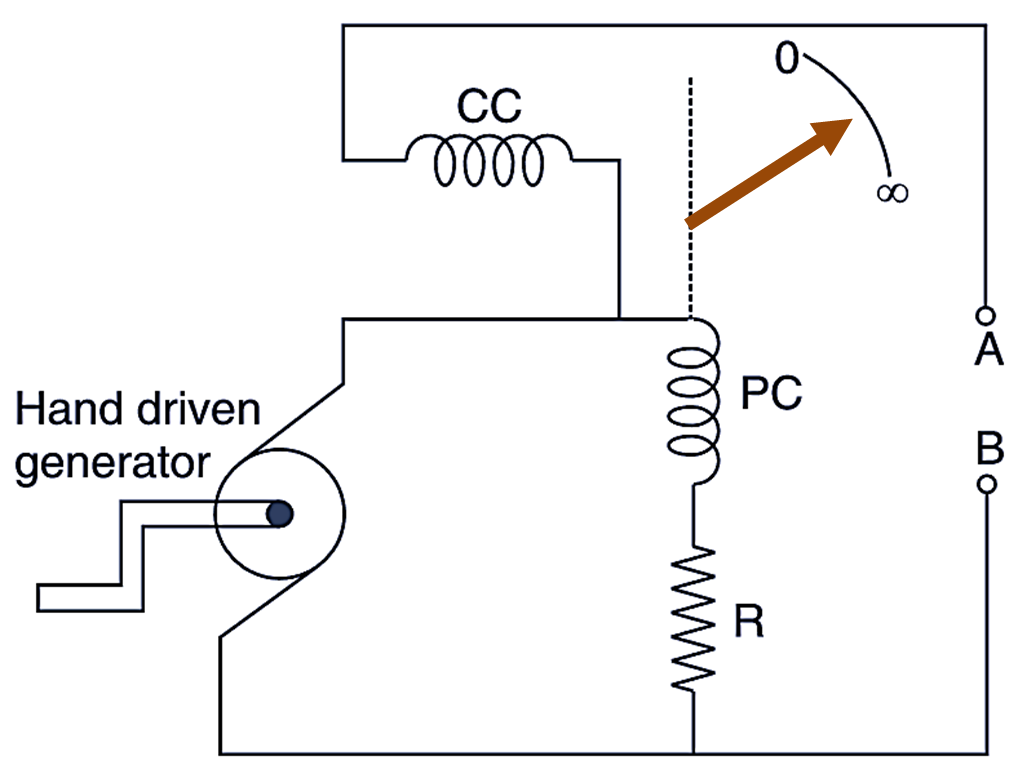
Fig. 1: Ohmmeter
The moving system of an ohmmeter consists of 2 coils i.e., potential coil (PC) and current coil (CC) fixed at right angles to each other. When current flows through these coils a turning moment (deflecting torque) is produced which moves the pointer on a scale calibrated from zero to infinity. The instrument also contains a hand driven generator which when turned by hand produces a voltage of about 500 V for the two coils. The PC is connected in series with a resistance R to extend the range of the instrument. The resistance under measurement is connected across terminals A and B.
Operation of Ohmmeter
When a current flows through the two coils, the magnetic field produced by PC creates an anticlockwise torque on the pointer, whereas the magnetic field produced by CC creates a clockwise torque on the pointer. The needle or the pointer takes a balance position. where the two torques are equal.
- If the resistance under measurement is infinite, the CC will carry no current the pointer will be governed only by the magnetic field of the PC and it will indicate infinity on the scale e.g., in an open circuit.
- When there is no resistance between A and B, then the magnetic field of CC will be very powerful and it will set the pointer at zero e.g., in a short circuit.
- The pointer will take up an intermediate position between 0 and ∞ according to the value of resistance under measurement.
The ohmmeter is a very useful instrument for measuring low/medium/high resistances as a single portable unit. It is also incorporated in many special ïnstruments like earth tester. megger etc.
Types of Ohmmeter
The ohmmeters may be of two types:
- Series type ohmmeter
- Shunt type ohmmeter
Series type ohmmeter
In this instrument, the resistance under test is connected in series with the meter and across terminals A and B as shown in Fig. 2. The indication of the instrument is dependent upon the magnitude of current through the meter, which in turn depends upon the value of the resistance for measurement.
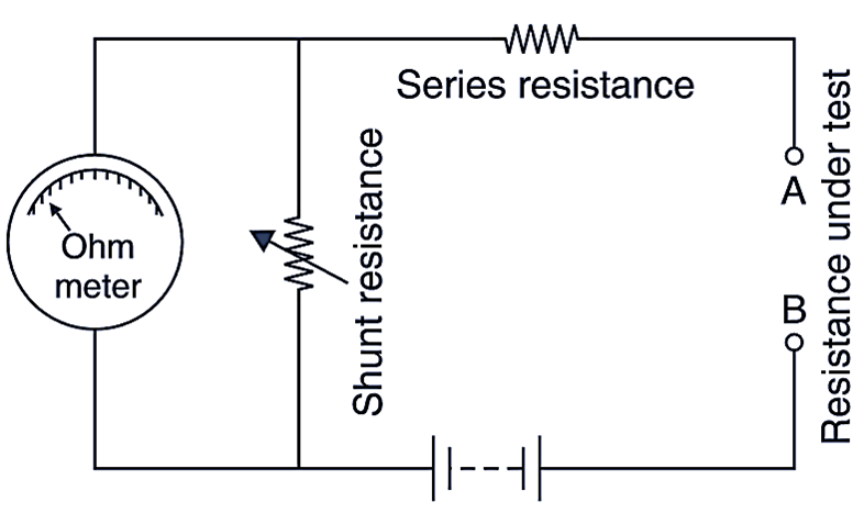
Fig. 2: Series type ohmmeter.
Shunt type ohmmeter
In this instrument, the resistance under test is connected in parallel to the meter cross terminals A and B (Fig. 3). A battery is connected in series with the meter. There is a switch S, so that to keep the battery from running down when the instrument is not in use.
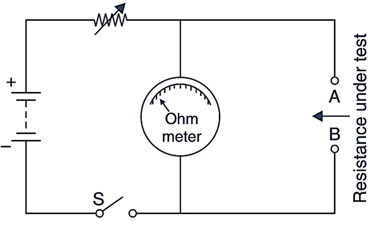
Fig. 3: Shunt type ohmmeter.
Simple Ohmmeter
The meter is used to measure the value of unknown resistance in ohms. Fig. 4 shows an arrangement of a simple Ohmmeter. It contains a moving coil type meter. The scale is calibrated in ohms. The meter is energised by a dry cell of 1.5 V. A variable resistance is connected in series with the moving coil instrument for zero adjustment. The deflecting torque of the instrument depends upon the value of the current in the moving coil, the current is maximum when both the terminals are short circuited. When an external resistance is connected series the value of current depends upon the resistance and current automatically decreases and the reading is obtained on the calibrated scale in ohms.
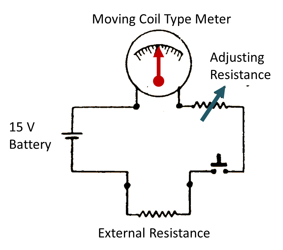
Fig. 1. Simple Ohmmeter