When pressure control valve is used to limit the pressure in a system to a prescribed maximum value by draining some or all the pump output to the reservoir tank when designed set pressure is reached, it is known as pressure relief valve (Fig. 1).
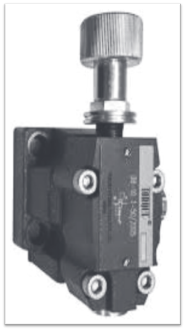
Fig. 1: Pictorial view of the pressure relief valve.
A pressure relief valve is the most widely used relief valve in many practical applications. It is a normally closed valve, which diverts the pump flow back to the reservoir to limit the pressure to a specified maximum limit (Figure 1).
Construction of Simple Pressure Relief Valve
The schematic diagram of a simple pressure-relief valve is shown in below figure 2.
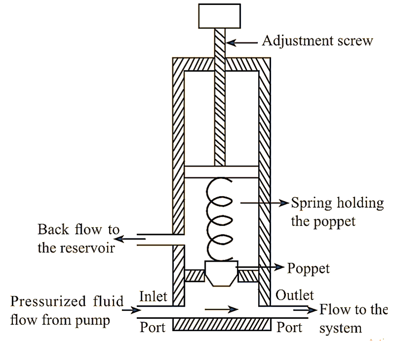
Figure 2: Pressure Relief Valve
The pressure relief valve mainly consists of a ball or poppet, compression spring and an adjustment screw. It is also provided with two ports, one is inlet port which allows the pump flow into the valve and the other one is outlet port connected to the reservoir. Spring is provided to keep the poppet or ball in its seat by the force applied by the compression spring. An adjusting screw is provided to adjust the spring force, generally equal to the desired operating pressure of the system.
Working of Pressure Relief Valve
The poppet or ball remains in its seat, when the pressure in the system is below the spring force. Thus, the flow from the pump is directed to the system (Fig. 2). When the system pressure rises to a value higher than the spring force, the poppet gets lifted from its seat. Thereby, pressurized liquid enters the valve and flows to the reservoir through outlet port. Flow to reservoir continues as long as pressure in the system falls to a value lower than the spring force. Diversion of flow keeps the system safer when high pressures are developed.
The pressure at which the poppet begins to open is known as cracking pressure. The pressure at which the full pump flow is allowed through the valve seat is known as the full flow pressure of the valve, it is the maximum permitted pressure level by the relief valve.
Working Principle of Pressure Relief Valve
It works on the principle of lifting the valve element with oil pressure (Poil) against the spring (designed set) pressure (Pspring). When set pressure is greater than oil pressure, the valve is closed and opens when oil pressure exceeds the set pressure (Figure 3).
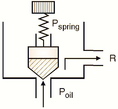
Fig. 3: Principle of the pressure relief valve.
A pressure relief valve is a safety device used for protecting the system from excess pressure by diverting the flow of fluid back to the tank. During working, the valve is closed by a poppet by the force of a stiff compression spring to stop the fluid flow.
The spring force can be adjusted. When the pressure of fluid increases and exceeds the preset value of spring force, the valve gets opened, thus allowing the fluid flow through the outlet. This fluid is allowed into the reservoir, until the desired set pressure is achieved. Thus, the constant pressure is maintained throughout the system.
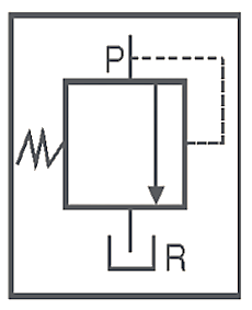
Symbol of Pressure relief valve
Function of Pressure Relief Valve
When working pressure is exceeded by the pump oil pressure, it may cause hazards and damage of pipe lines and other components hence as a safety device, pressure relief valves are provided. It will relief pressure which is more than working pressure to the reservoir by lifting valve element. It will divert flow to the reservoir till the pressure is equal to the working pressure.
Types of pressure relief valve
- Direct operated pressure relief valve
- Pilot operated pressure relief valve
Direct operated pressure relief valve
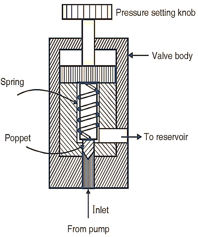
Fig. 4: Construction of pressure relief valve
Construction:
It consists of the following main parts (Fig. 4):
Poppet: It is the main valve component of conical shape seated in the valve body. Its upper end is attached to the spring which exerts compressive force on it.
Spring: It is provided to set the designed pressure of the hydraulic system with the help of setting knob.
Pressure setting knob: It is a screw which can be adjusted to set the spring force as per requirement.
Valve body: It is provided with the inlet and drain ports and accommodate all above components.
Limitations of Direct operated pressure relief valve
- They are suitable where the flow rate and the system are reasonably smaller.
- There is no much variation in system pressure of how rate.
- It is not feasible to use bigger spring due to more space requirement for higher system pressure.
To overcome above problems, pilot operated pressure relief valve are designed and used.