Semiconductor Fuse is a power device required to be protected against large currents. The semiconductor fuse is the fast-acting fuse that is normally used to protect the semiconductor devices. The physical appearance of a semiconductor fuse is as shown in Fig. 1.
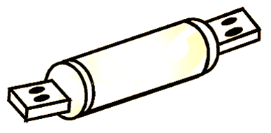
Fig. 1: Semiconductor fuse.
As the fault current increases, the fuse connected in series with the device is open circuited to protect the device. The nature of fuse current is shown in Fig. 2.
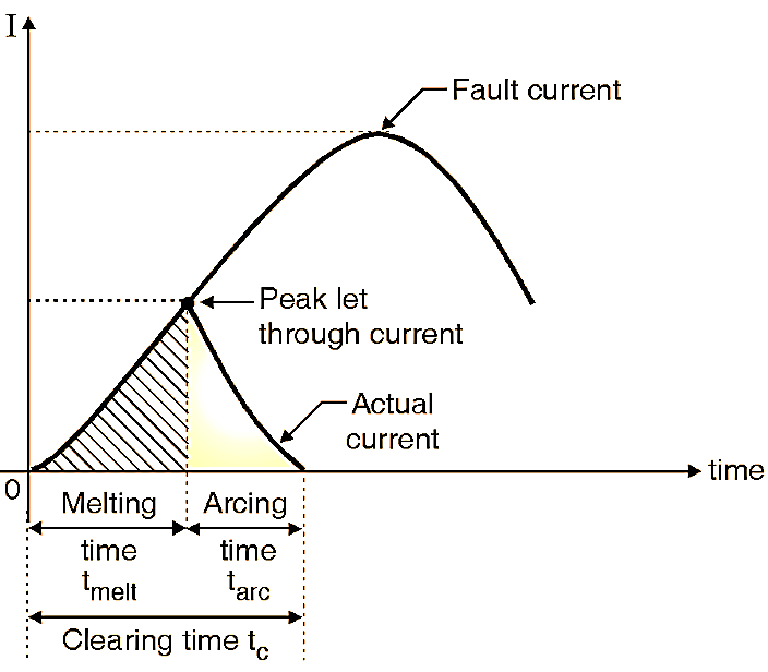
Fig. 1: Fuse Current.
Working of Semiconductor Fuse
As the fault current flowing through the fuse increases, the fuse temperature also rises upto t = tmelt as shown in Fig. 2. At t = tmelt the fuse melts and acring takes place across the fuse. Due to this arc, the fuse impedance is increased and the fuse current will reduce. But the arc voltage remains formed across the fuse. The generated heat vapourizes the fuse element. This increases the arc length and further reduces the current. Due to this cumulative effect the arc extincts in a very short time. The arcing is complete during the time interval tarc and the fault is cleared i.e. current reduces to zero. The fuse gets open circuited. The clearing time is given by.
tc = tmelt+ tarc
For successful protection of a device, t should be shorter than the time required for the power device to get damaged due to excessive heat produced by the fault current.
Current-time curves of Semiconductor Fuse
The selection of a fuse is done with the help of the current-time curves shown in Fig. 3. Fig. 3 (a) shows the current-time characteristics of a device and its fuse where the device can be protected for all the values of overload currents. This type of protection is normally used for low power converters. Fig. 3 (b) shows the curves used by a more common system in which the fuse is used for short circuit protection at the beginning of the fault. The normal overload protection is taken care of by circuit breaker.
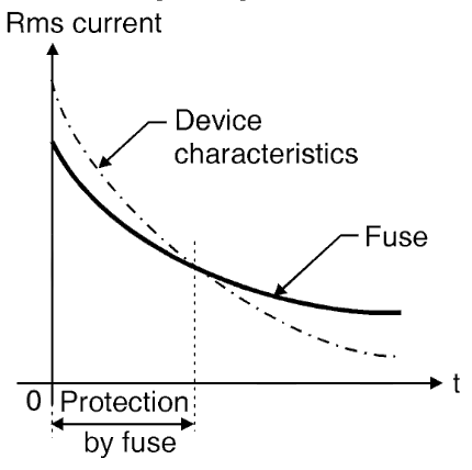
(a)
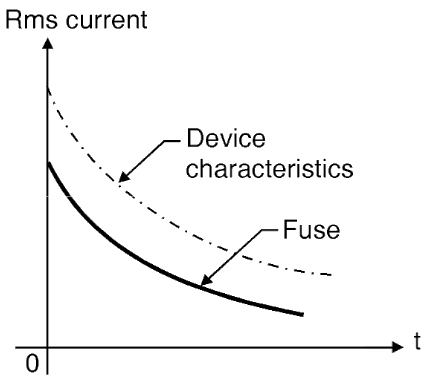
(b)
Fig. 3: Semiconductor Fuse Characteristics.
Selection of Semiconductor Fuse
The selection of fuse is carried out on the basis of following requirements:
- The fuse must continuously carry the rated current of the device under normal operating condition.
- The I2t value of the fuse, should be less than the rated I2t of the device, so that the fuse will blow before the device.
- The fuse should be able to withstand the voltage that appears across it after the arc extinction.
The peak arc voltage should be less than the peak voltage rating of the device, so that the device does not get damaged. All these requirements are fulfilled by a special type fuse called semiconductor fuse.
The overcurrent capability of thyristors is better than that of a transistor. So protecting transistors, MOSFETs and IGBTs is more difficult than protecting the thyristors. The fusing may not be able to protect the transistors, MOSFETs and IGBTs. Hence a special circuit called crowbar circuit is used to protect transistors, MOSFETs and IGBTs.
Note: In some applications we have to add an inductance in series with a device in order to protect it against the excessive di/dt stress.