In this topic, you study Regulated Power Supply – Circuit Diagram, Working & Waveforms.
The unit containing the circuits which convert the ac supply voltage into dc regulated voltage at required level is termed as dc regulated power supply. The block diagram of d.c. regulated power supply is shown in Fig. 1 and the nature of voltages at various points is also shown in Fig. 2.
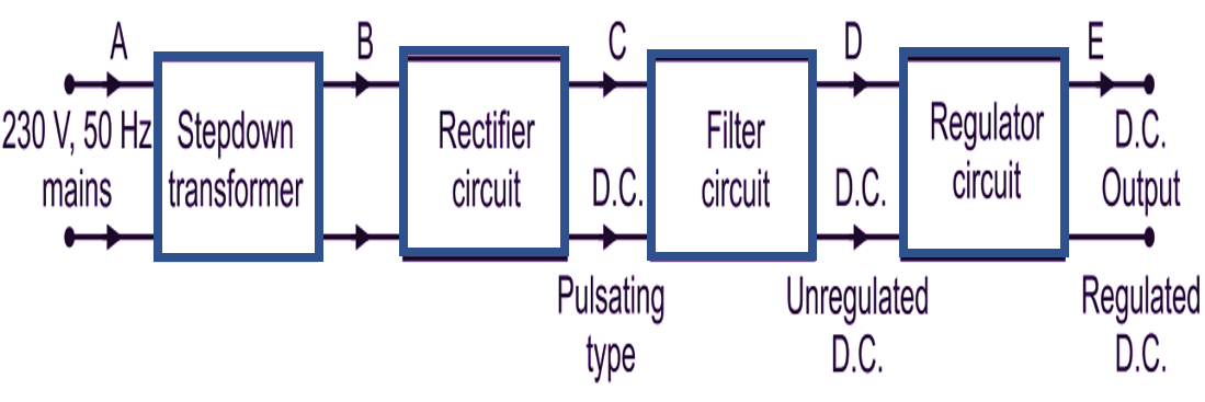
Fig. 1: Block diagram of a d.c. regulated power supply
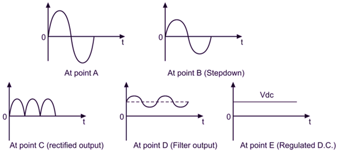
Fig. 2
Transformer
The a.c. voltage 230 V, 50 Hz from mains is connected to the primary of the transformer. Transformer used is a step-down transformer, which steps down the a.c. voltage to the required level. Thus with suitable turns ratio, we get bidirectional a.c. voltage at secondary of the transformer.
Rectifier Circuits
The bidirectional or voltage from the secondary of the transformer is converted into a unidirectional pulsating d.c. using a rectifier. A rectifier is a circuit, which uses one more diodes to convert a.c. voltage into pulsating dc. Rectifiers are classified depending upon the period of conduction as half-wave rectifier and full-wave rectifier. Half-wave rectifier converts an a.c. voltage into unidirectional pulsating d.c. voltage using only one half of the applied a.c. voltage whereas full-wave rectifier uses both half cycles of the applied a.c. voltage. A pulsating d.c. output of rectifier contains large ripples. These ripples are removed by filter circuits.
Filter Circuits
Filter is a circuit which reduces the ripple content in the pulsating d.c. and tries to get pure d.c. voltage. But still, the filter output contains some ripple and this voltage is called as unregulated d.c. voltage. Some important types of filters are:
- Inductor filter,
- Capacitor filter,
- π-type filter.
Regulator Circuit
The output of the filter is fed to a regulator circuit. The voltage regulator is a circuit which gives the output voltage constant in spite of the changes in load current or input voltage. Hence the output of the regulator is steady d.c. output i.e. regulated output. The output of a regulator is called d.c. supply to which load can be connected. Various types of regulator circuits are zener diode shunt regulator, transistor shunt regulator, transistor series regulator, etc. Now-a-days, complete regulator circuits are available in the integrated circuit (IC) forms.