The transmission lines have large length and it is exposed to different atmospheric conditions. So chances of occurrence of faults are more. The requirements of transmission line protection scheme are:
- In the event of short circuit in any sections, the CB closest to that fault should open and other CBs should be in closed position.
- If CB nearest to fault fails to open, the back up protection CB should operate.
- The relay operating time should as short as possible.
The differential protection scheme can satisfy above conditions. The transmission line can be divided into number of sections. Each section can be protected by differential protection scheme. But since length of transmission line is large, such scheme becomes uneconomical so following methods are used. Distance protection is applied where time lag cannot be permitted.
- Time graded overcurrent protection.
- Current graded overcurrent protection.
- Distance protection.
Time graded overcurrent protection is used as main protection for distribution lines and back up for main lines where main protection is of distance type. Current graded protection is used where a time lag can be permitted and instantaneous operation is not necessary. Distance protection is applied where time lag cannot be permitted.
Time Graded Overcurrent Protection
The line or feeder is divided into number of sections. Overcurrent relays are provided for each section. On occurrence of fault in any section, the respective relay operates and gives trip signal to CB. The CB then opens and isolates the faulty part. Fig. 1 shows time graded overcurrent protection scheme.
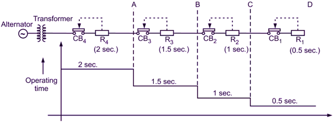
Fig. 1: Time Graded Overcurrent Protection
The entire feeder is sectionalised (i.e. AB, BC, CD). Definite time relays are used for individual section which gives trip signal to respective CB. Relay R1 has operating time of 0.5 second, for R2 it is 1 sec and so on. If fault occurs in section CD, that section will be isolated in 0.5 sec by R1 and CB1. The remaining relays will not operate because their operating time is higher. If R1 and CB1 fails to operate even after 0.5 seconds, R2 operates after 1 second causing CB2 to open. Thus, acts as back up protection. In the similar way if R2 and CB2 fails to operate in 1 second, R3 and CB3 will operate.
Drawbacks of Time Graded Overcurrent Protection
- If feeder is having large length or more number of sections, the operating time near supply side point is more. For our case it will be 2 second which is appreciable.
- If a fault say line to ground fault occurs in the section near the transformer, or source, in that cause amount of fault current will be more because line impedance is less. Ideally, the operating time should be less for more amount of fault current. If feeder is having large length and number of sections are more, this condition can not be satisfied. So time graded principle is applicable where impedance between substation is low i.e. feeder length is less.
Note: In addition to relay operating time, the CB operating time should also be considered. In most of the cases it is necessary to limit the maximum tripping time to 2 sec.
Current Graded Overcurrent Protection
The drawback of time graded system is that relay near the source operates at last and the fault current level is high near the source. The relays used for this scheme are high speed instantaneous over current relays. The operating time for every relay is same. Consider a feeder which is divided into sections A, B, C (Fig. 2). The current setting for a relay corresponds to the fault current level for the respective section. Relay R2 should operate for faults between B and C. But it should not operate for faults beyond C. Similarly, relay R1 should operate for faults between A and B. The relay R3 should operate for faults beyond C. But above operation is difficult to obtain because of following reasons:
- Relay R1 is not able to differentiate between faults very close to B i.e. on either side of B. If fault in section BC is very close to B, the relay R1 considers that the fault is in section AB and it operates, which is not desired. This happens because there is a very little difference in fault currents if a fault occurs at the end of section AB or in the beginning of section BC.
- It is difficult to evaluate accurate value of fault current because the conditions may be different for respective faults.
- During fault, transients are produced and relay performance is affected.
The current graded system is used where impedance between substations or sections is sufficiently large to create a marginal difference in fault current.
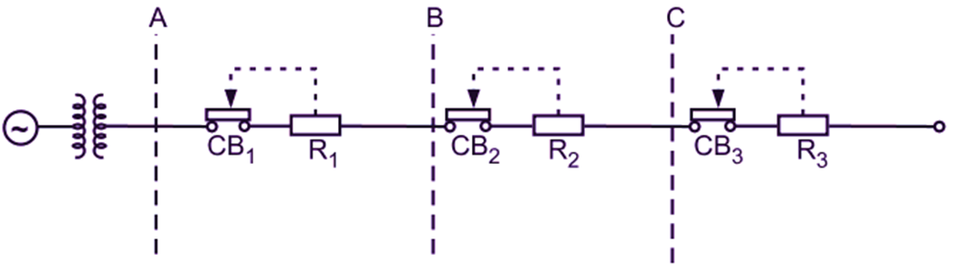
Fig. 2: Current Graded Principle
Pilot Wire Protection
It uses differential protection principle i.e. under normal working conditions the current entering one end of line is equal to that leaving the other end. If fault develops, the balance is disturbed and the difference of incoming and outgoing current flows through the relay coil and trip signal is produced that operates the CB and thus faulty part is isolated. Pilot wire protection methods: Following methods are used
- Mertz-Price voltage balance system.
- Translay scheme.
Mertz-Price voltage balance system:
Fig. 3 shows arrangement for this scheme. Two identical CTs are placed at both ends of the line. The CT secondaries are connected in phase opposition i.e. their secondary voltages oppose each other.
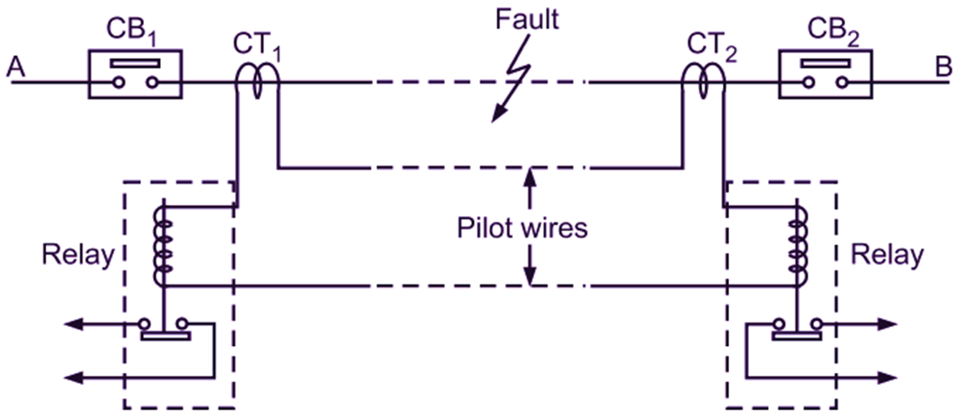
Fig. 3: Mertz-Price voltage balance system
Relay coils are connected in CT secondaries as shown. Under normal conditions, current entering from A is equal to current leaving from B. The CT secondary voltages are equal in magnitude and opposite in phase, so no current flows through the relay coils. Under normal conditions, current entering from A is equal to current leaving from B. The CT secondary voltages are equal in magnitude and opposite in phase, so no current flows through the relay coils. When fault occurs between A and B, this causes CT1 secondary current to increase compared to CT2, so voltages of CT secondaries are no longer equal. Circulating current flows in CT secondary circuit through pilot wires and relay coils. The relays R1 and R2 operate causing operation of CB1 and CB2. This faulty part is isolated.
Advantages:
- This scheme can be used for ring system and parallel feeder system.
- Provides instantaneous protection for ground faults.
Disadvantages:
- CTs should be identical,
- It is expensive.
- It cannot be used beyond 33 kV.
- If pilot wire breaks, malfunctioning occurs.
- Not suitable for very long lines.
This scheme can be used for 3-phase system also. In that case total 6 CTs and 6 relays will be connected in the three phase line.
Translay Scheme
It uses overcurrent induction relays. The CT secondaries are connected to the windings which are placed on central limb of the induction relay. Refer Fig. 4. Each induction relay has two electromagnets E-shaped and C-shaped. E-shaped electromagnet central limb carries winding A or A’ which are connected in CT secondaries. The connections are made such that there is summession transformer action. All the CTs are identical. The central limb also carries another winding BB’ just below AA. This BB’ windings and CC’ windings are connected in series through pilot wires and in phase opposition i.e. their voltages act in opposite direction.
Operation of Translay Scheme
Under normal working conditions, CT secondary currents are equal. These currents produce flux that links with B, B’ and e.m.f. is induced in these coils. Since B and B’ are in phase opposition, there is no current flowing in the circuit of these windings i.e. no current flows through C and C’. So there is no torque produced on the disc. When fault occurs, the voltages induced in B and B’ are no longer the same, corresponding difference current flows through C and C’. And due to induction action a torque is produced on the disc, the disc rotates and trip circuit contacts are closed. The respective CBs operate such that faulty section is isolated.
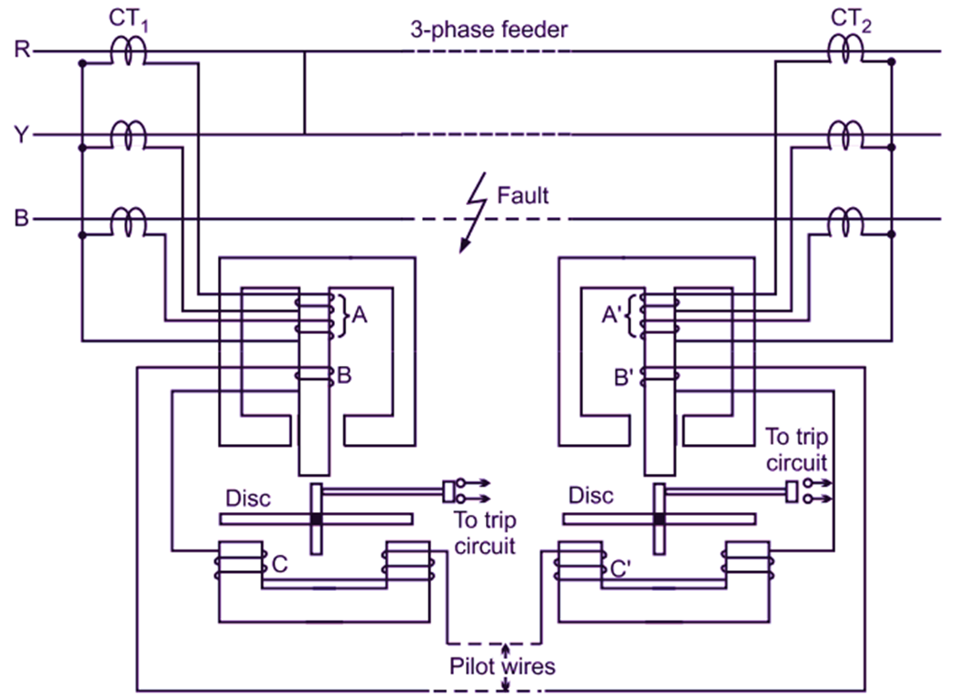
Fig. 4: Translay Scheme
Advantages of Translay Scheme
- It is economical because only two pilot wires are used.
- Normal CTs can be used.