The major drawback of the SCR is that as a single SCR cannot be used to control the a.c. power in load. However, in a.c. systems, it is often desirable and necessary to exercise to control over both positive and negative half cycles. For this purpose, a semiconductor power electronics device called TRIAC is used. The TRIAC is an acronym that has been coined to identify the TRIode AC semiconductor switch. Thus TRIAC is an abbreviation of Triode AC Switch. The word Tri’ indicates that the device has three terminals and the word ‘AC’ means that the device controls the alternating current, or can conduct current in either direction.
In thyristor family, after SCR, TRIAC is the most widely used power electronics device for a.c. power control. TRIAC is a three terminal semiconductor or bilateral switching device which can control alternating current in a load, when triggered either by a positive or negative gate pulse irrespective of the polarity of the voltage applied across its main terminals. In operation, TRIAC is similar to two SCRs connected in antiparallel. The TRIACs are now available with the reasonably large current ratings upto 25 A and voltage ratings upto 500 V.
Construction of TRIAC
TRIAC is yet another thyristor family device which is used extensively for the control of power in a.c. circuits. TRIAC is the word derived by combining the capital letters from the words TRIode and AC. TRIAC is a bidirectional switching semiconductor device. Fig. 1 shows a cross-sectional view of a TRIAC. The TRIAC is usually turned ON by applying a positive or negative voltage to the gate with respect to MT1.
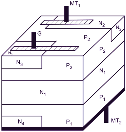
Fig. 1: Cross-sectional view of a TRIAC
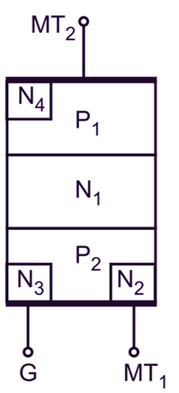
(a) Basic structure
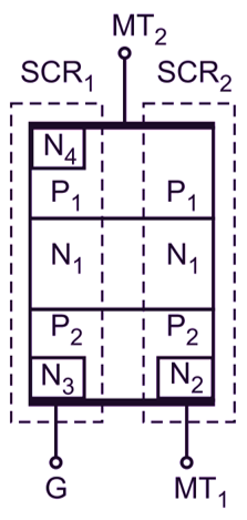
(b) Equivalent structure
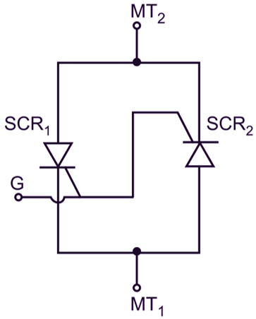
(c) Equivalent circuit
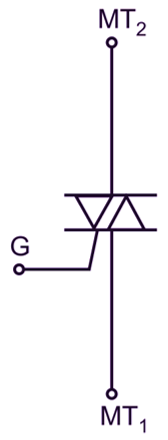
(d) Symbol
Fig. 2: Structure of a TRIAC
Principle of Operation of TRIAC
The operation of a TRIAC may be explained from Fig. 3. The series resistor RL may be connected as a load in series with the terminal MT2. The terminal MT2 may be made positive or negative with respect to MT1.
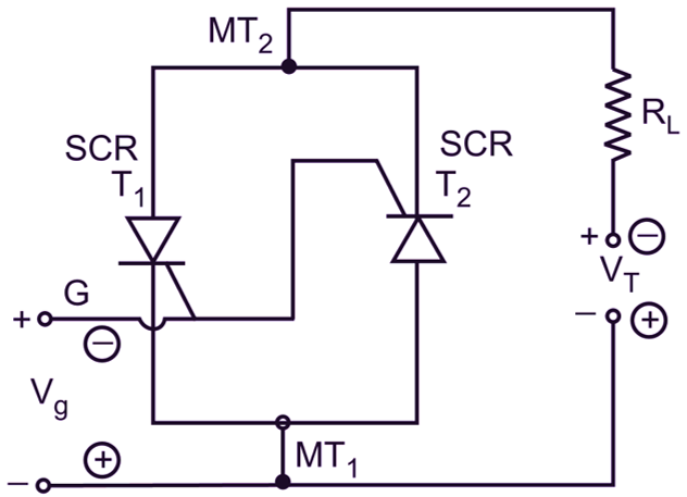
Fig. 3: Operating principle of a TRIAC
The TRIAC is said to be forward biased when terminal MT2 is positive with respect to MT1, and the terminal G is open i.e. Vg = 0. The SCR T1 will be forward biased whereas the SCR T2 will be reverse biased. As the forward voltage VT is less than the forward breakover voltage VBO, the SCR T1 will not conduct. Also SCR T2 will not conduct. Hence, the TRIAC will be in OFF state. As the forward voltage approaches the bleakover voltage, the SCR T1 will conduct the current and it will be in ON state. So, the TRIAC will be in ON state. If a positive or negative trigger pulse is applied at gate G, the SCR T2 will conduct the current and it will be in ON state, so the TRIAC will be in ON state.
The TRIAC is said to be reverse biased when the terminal MT2 is negative with respect to MT1 and the terminal G is open, i.e. Vg = 0. The SCR T1 will be reverse biased whereas the SCR T2 will be forward biased. As the reverse voltage VT is less than the reverse breakover voltage (- VBO), the SCRs T2 as well as T1 will not conduct. Hence, the TRIAC will be in OFF state. As the reverse voltage approaches the breakover voltage, the SCR T2 will conduct the current and it will be in ON state. So the TRIAC will be in ON State. If a positive or negative gate pulse is applied at gate G, the SCR T2 will conduct the current and it will be in ON state. So, the TRIAC will be in ON state. It may be noted that a gate current pulse of specified amplitude and of either polarity (positive or negative) will trigger the TRIAC into conduction (ON) State, assuming that TRIAC is in OFF state. Also the TRIAC conducts in both directions for either polarity (positive or negative) of voltage on terminals MT1 and MT2.
Modes of Operation of TRIAC
The TRIAC can be turned ON by applying positive or negative gate current pulse at a gate by keeping the TRIAC in either forward or reverse biased conditions. The turn ON process of TRIAC in four modes can be explained as follows:
Mode 1 (Quadrant I):
Consider the structure of a TRIAC as shown in Fig. 4. When the terminal MT2 is positive with respect to the terminal MT1, the junctions P1N1 and P2N2 ate forward biased but the junction N1P2 is reverse biased.
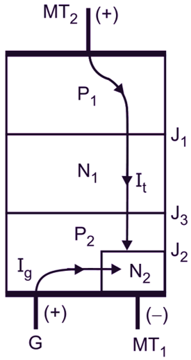
Fig. 4: TRIAC in Mode 1
When the positive gate current is applied at the gate G, the gate current Ig flows through the junction P2N2. The TRIAC starts conducting through the layers P1N1P2N2 due to positive regenerative action. The TRIAC is more sensitive in this mode of operation as compared to other modes of operation. This is the recommended method of triggering the TRIAC, if its conduction is desired in first quadrant. The TRIAC can be turned ON at a lower gate current at a fixed forward voltage VT, i.e. VT < VBO.
Mode 2 (Quadrant I):
Consider the structure of a TRIAC as shown in Fig. 5.
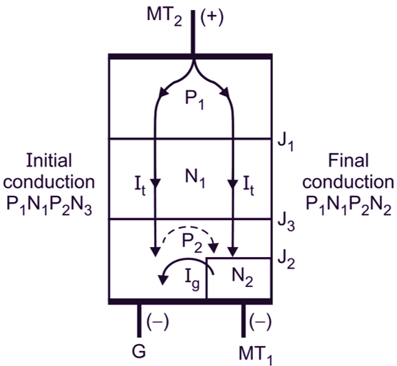
Fig. 5: TRIAC in Mode 2
When the terminal MT2 is positive with respect to the terminal MT1, the junctions P1N1 and P2N2 are forward biased, but the junction N1P2 is reverse biased. When the negative gate current is applied at the gate G, the gate current Ig flows through P2N3. The TRIAC starts conducting through P1N1P2N3 layers initially. The left hand side of layer P2 is more positive as compared to its right hand side as the terminal MT1 is negative on right hand side. Because of this potential gradient, a current is established in P2 layer which is shown by dotted line in Fig. 5. As a result, the right hand side of TRIAC starts conducting through P1N1P2N2 layers and stays in ON State. TRIAC is less sensitive in this mode of operation as it requires more gate current to turn ON at the same forward voltage VT as compared to Mode 1. The turn ON delay is also more in this Mode 2. This mode of operation is called junction gate operation, which involves high switching losses and therefore this mode of operation is not normally used.
Mode 3 (Quadrant II) :
Consider the structure of a TRIAC as shown in Fig. 6.
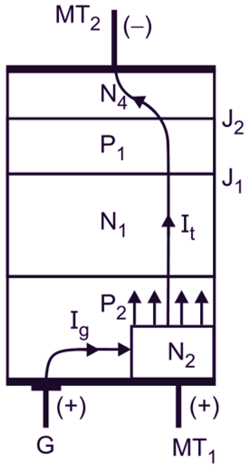
Fig. 6: TRIAC in Mode 3
The terminal MT2 is negative with respect to the terminal MT1 and the positive gate current pulse is applied at the gate G. The junction P2N2 is forward biased by the external positive gate current. Because the terminal MT1 is connected to layer N2, the layer N2 injects electrons into P2 layer as shown by dotted arrows. This causes the reverse biased junction N1P1 to breakdown. As a result, the TRIAC starts conducting through P2N1P1N4 layers and stays it in ON state. TRIAC is less sensitive in this mode of operation.
Mode 4 (Quadrant III) :
Consider the structure of a TRIAC as shown in Fig. 7.
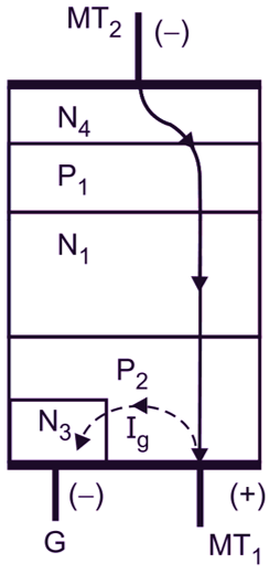
Fig. 7: TRIAC in Mode 4
The terminal MT2 is negative with respect to the terminal MT1 and the gate current pulse is also negative. Here the layer N3 acts as a remote gate. The external negative gate current pulse of gate G causes the gate current to flow through the junction P2N3. This causes the junction P2N3 to become forward biased. The TRIAC starts conducting through the layers P2N1P1N4 and stays in ON state. TRIAC is more sensitive in this mode of operation as compared to that of Mode 3. In all the four modes of operation, the sensitivity of a TRIAC is highest in first quadrant (Mode 1) with positive gate current and also in third quadrant (Mode 3) with negative gate current. The degree of sensitivity is indicated by the magnitude of gate current. The TRIAC operates in four modes of operation as explained above. Thus the triggering modes of a TRIAC are as given below:
| MT2 | MT1 | Gate | Quadrant | Mode |
| Positive | Negative | Positive | I | 1 |
| Positive | Negative | Negative | I | 2 |
| Negative | Positive | Positive | III | 3 |
| Negative | Positive | Negative | III | 4 |
V-I Characteristics of TRIAC
It is the curve between the voltage applied across the two main terminals and the current flowing through the TRIAC at constant gate current. The TRIAC has two types of V-I characteristics, namely forward and reverse characteristics.
Experimental setup for forward characteristics of a TRIAC:
The experimental set-up for plotting the forward characteristic of a TRIAC is as shown in Fig. 8. Initially, adjust the positive gate voltage to zero.
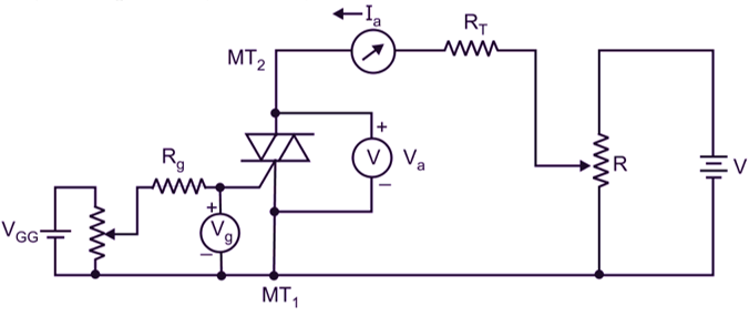
Fig. 8: Experimental setup for forward characteristics of a TRIAC
Then increase the applied voltage across the TRIAC in small suitable steps. At each step, record the value of TRIAC current and the voltage across it. Now, if we plot a graph with the positive voltage across a TRIAC along the horizontal (X) axis and the TRIAC current along the vertical (Y) axis, we obtain a curve in 1st quadrant as shown in Fig. 9. A similar procedure may be used to obtain curves marked Ig, Ig1, and Ig2 for different values of gate current.
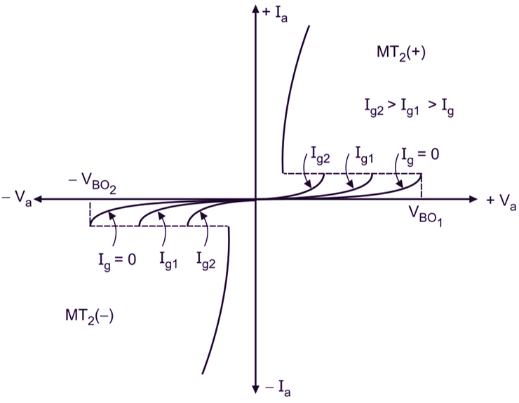
Fig. 9: Static V-I characteristics of a TRIAC
Experimental setup for reverse characteristics of a TRIAC:
The experimental set-up for plotting the reverse characteristics of a TRIAC is shown in Fig. 10. Initially, adjust the negative gate voltage to zero. Then increase the applied negative voltage across the TRIAC in some suitable steps. At each step, record the value of TRIAC current and the negative voltage across it.
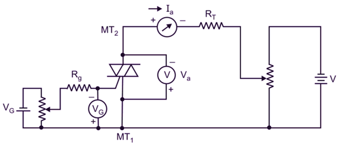
Fig. 10: Experimental setup for reverse characteristics of a TRIAC
Now, if we plot a graph with negative voltage across a TRIAC along the horizontal (X) axis and the negative TRIAC current along the vertical (Y) axis, we obtain curves for different values of negative gate currents as shown in 3rd quadrant of Fig. 9.
Forward and reverse characteristics:
The forward and reverse V-l characteristics Of a TRIAC are as shown in Fig. 9. The following are the important points that are observed from the forward characteristics
- The curve is identical to the forward characteristics Of SCR.
- The TRIAC is OFF until the applied voltage exceeds the breakover voltage.
- AS the applied voltage exceeds the breakover voltage, the TRIAC turns ON and the voltage drop across the TRIAC decreases to a low value of holding voltage. The TRIAC forward current increases to a value determined by the supply voltage and the load resistance.
- As the value of gate current is increased above zero, the breakover voltage is lowered like SCR. The TRIAC is never operated with the zero gate current. When gate current of a suitable value is applied, usually in the form of pulses, the TRIAC turns ON at much lower breakover voltage.
Note: The following are the important points that are observed from reverse characteristics:
- The curve is identical to the reverse characteristics of SCR.
- The TRIAC is OFF until the applied negative voltage exceeds the break-over voltage.
- As the applied negative voltage exceeds the breakover voltage, the TRIAC current decreases to a low value of holding current. The TRIAC reverse current increases to a value determined by the supply voltage and load resistance.
- If the value of gate current is increased above zero, the breakover voltage is lowered. Like SCR, the TRIAC is never operated with the zero gate current. When the negative gate current of a suitable value is applied usually in the form of pulses, the TRIAC turns ON at much lower breakover voltage.
Applications of TRIAC
The TRIAC has an important property that it can conduct current in either forward or reverse directions, depending upon the polarity of the voltage across its main terminals. This property makes the TRIAC very useful for industrial applications. Some of the important applications of a TRIAC are as given below.
- as static switch.
- for phase control.
- for speed control Of AC motor.
- for light-dimming control.
- for thermostat/heater control.
- for liquid level control.
- for AC power control.
- for electronic change over of transformer tap.
- as a high power lamp switch.
- in battery charger cum emergency light system.
- in flasher circuit.
- as a proximity detector.
Advantages of TRIAC
The advantages of a TRIAC are as given below :
- It needs a single heat sink of slightly larger size, whereas the anti-parallel SCR pair needs two heat sinks of slightly smaller sizes, but due to the clearance total space required is more for SCRs.
- It needs a single fuse for protection and this also simplifies the construction.
- It can be triggered with positive or negative polarity gate voltages.
- In some d.c. applications, SCR is required to be fitted with a parallel diode or protect against reverse voltage, a TRIAC used may work without a diode as a safe breakdown in either direction is possible.
- It can conduct current in both directions.
- It can control a.c. power as well as d.c. power.
- It can be triggered by negative or positive gate voltage.
- It controls more power than that of SCR.
- It needs a single heat sink of slightly larger size than that of a SCR.
Disadvantages of TRIAC
The disadvantages of TRIAC are as given below :
- It has low (di/dt) rating as compared to SCRs.
- It is not available in higher ratings.
- Its trigger circuit needs careful consideration as it can be triggered in either direction.
- Its reliability is less than that of SCR.
- It cannot be used for power controlling of inductive circuits or motor loads.
- It is costly than that of SCR.
- It has low (dv/dt) ratings.