Schmitt trigger uses positive feedback in its circuit. Hence it is also called as regenerative comparator. Figure (1) shows an Op-amp Schmitt trigger.
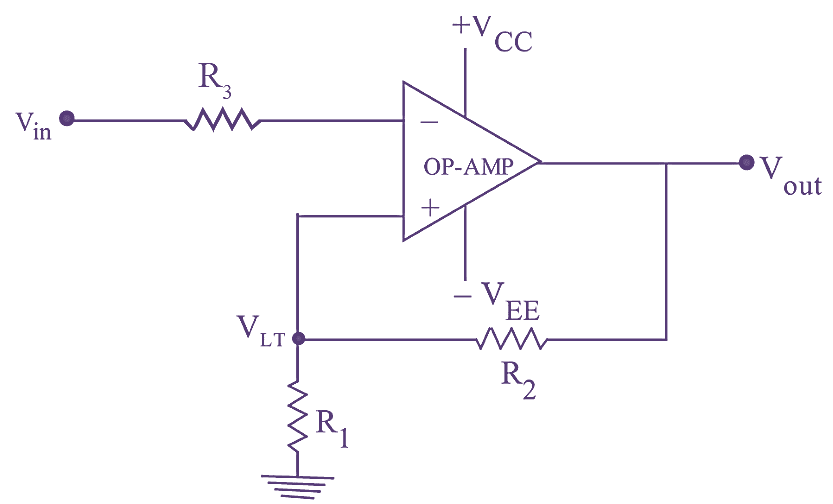
Figure 1: Schmitt Trigger.
The input voltage Vin, is applied to the inverting input terminal and feedback voltage is applied to the non-inverting input terminal. Since the positive feedback is given to the non-inverting input, the output is saturated either in the positive or negative direction. If the output is positively saturated, positive voltage called upper threshold voltage VUT is fed back to the non-inverting input terminal.
As long as the input voltage is less than the tipper threshold voltage, the output voltage will remain positively saturated.
As the input voltage is increased slightly, then a point is reached where the input voltage is more positive than the upper threshold point. When this occurs, op-amp is driven into saturation as the error voltage changes polarity. The negative output is fed back through the voltage divider formed by R1 and R2, to the non-inverting input terminal. This negative voltage is called lower threshold voltage. VLT, The output will remain in this state as long as input voltage is more positive than the lower threshold voltage. The values of the two threshold voltage levels i.e., VUT and VLT. can be determined and adjusted by selecting proper values of R1 and R2.
Thus,
\[{{V}_{UT}}=\frac{+{{V}_{sat}}{{R}_{1}}}{\left( {{R}_{1}}+{{R}_{2}} \right)}\]
If reference voltages is included,
\[{{V}_{UT}}=\frac{{{V}_{ref}}{{R}_{1}}}{{{R}_{1}}+{{R}_{2}}}+\frac{{{R}_{2}}{{V}_{sat}}}{{{R}_{1}}+{{R}_{2}}}\]
\[{{V}_{LT}}=\frac{-{{V}_{sat}}{{R}_{1}}}{\left( {{R}_{1}}+{{R}_{2}} \right)}\]
\[{{V}_{LT}}=\frac{{{V}_{ref}}{{R}_{1}}}{\left( {{R}_{1}}+{{R}_{2}} \right)}-\frac{{{R}_{2}}{{V}_{sat}}}{{{R}_{1}}+{{R}_{2}}}\]
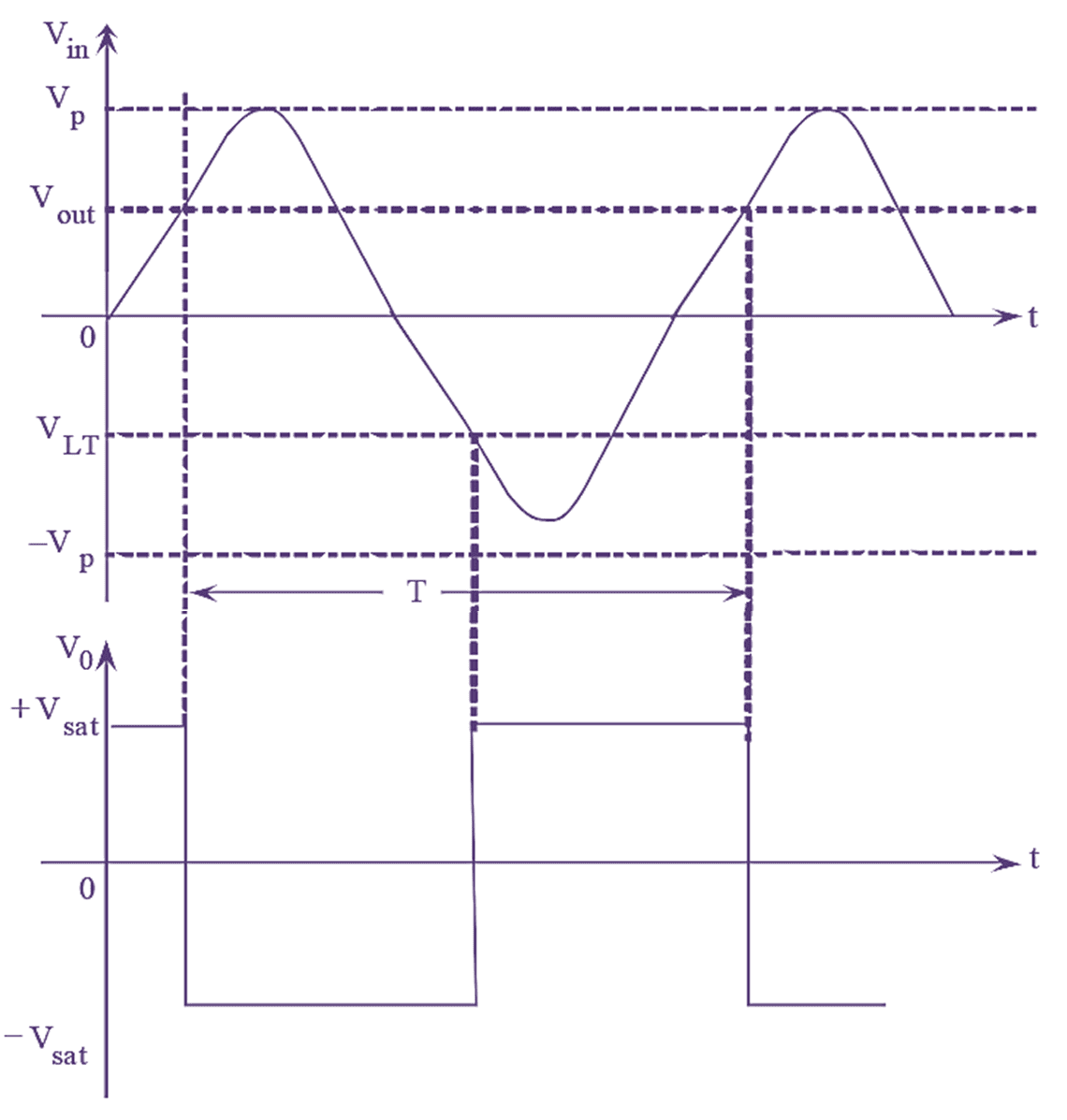
Figure 2: Schmitt Trigger input & output waveforms.
If the input applied is purely sinusoidal, the input and output waveforms for inverting Schmitt trigger is as shown in figure 2.
The difference between the UTP (Upper Triggering Points) and LTP (Lower Triggering Point) levels is known as the hysteresis of the circuit. Zero hysteresis is obtained if both upper and lower triggering points are equal. Hysteresis voltage is the difference of UTP and LTP level i.e.,
\[{{V}_{H}}={{V}_{UT}}-{{V}_{LT}}\]