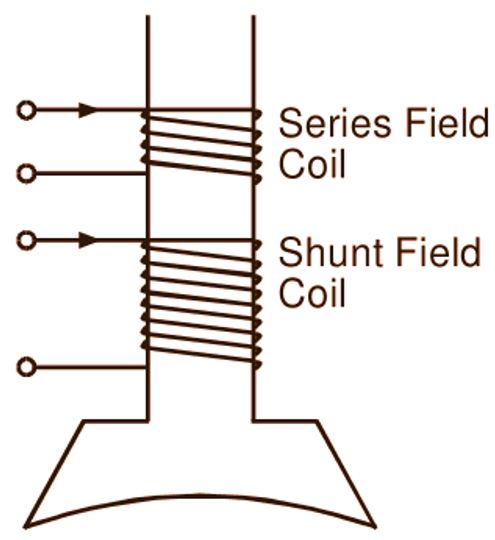
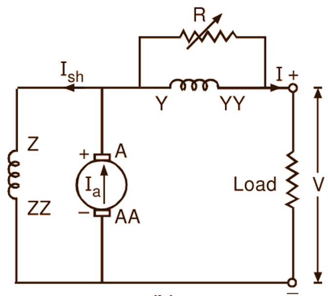
In the compound generator, when the shunt field m.m.f. assists the series field m.m.f. i.e. when the flux produced by these two m.m.f.s is additive, it is said to be cumulatively compounded. Fig. 1 (a) shows the relative current directions in the series and shunt field coils on each pole of a cumulative compound generator and Fig. 1 (b) shows diagrammatically the short-shunt type cumulative compound generator connected to a load.
(a)
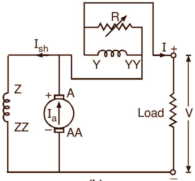
(b)
Fig. 1: (a) Relative current directions in series and shunt field coils on each pole of a cumulative compound generator, (b) Schematic representation of a cumulative compound generator (short-shunt)
From the study of the external characteristics of shunt and series generators, it follows that the shunt field alone gives the drooping characteristic while the series field alone gives the rising characteristic. Any characteristic in between these two can be obtained in a cumulative compound generator by the judicious combination of m.m.f.s provided by the shunt and series fields (Fig. 2).
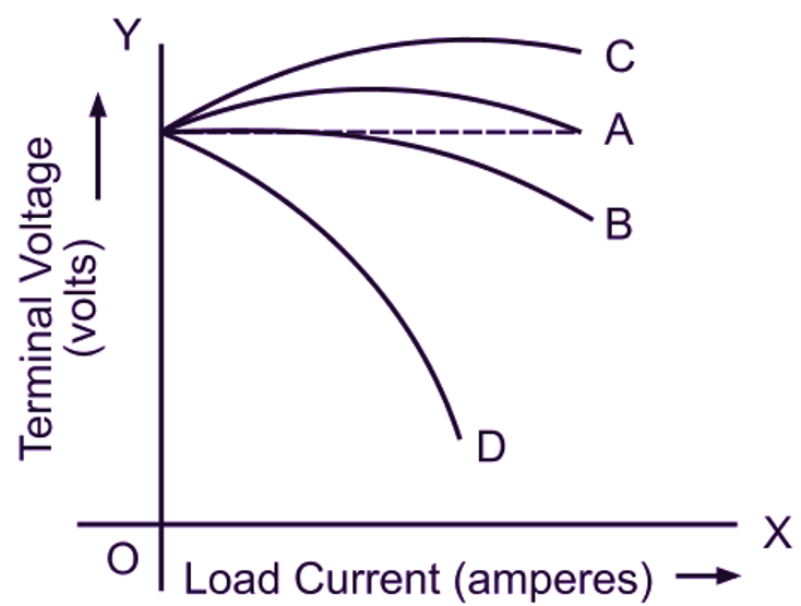
Fig. 2: External characteristics of a compound generator
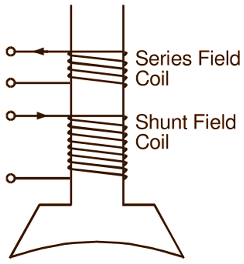
If the series field m.m.f. is so adjusted that the generator maintains its terminal voltage practically constant between no load and full load, then such a generator is said to be level compounded (Curve A). When the m.m.f. provided by the series field is such that the rated load voltage of the generator is less than its no-load voltage, the generator is said to be under compounded (Curve B) and when the rated load voltage of the generator is greater than its no-load voltage, the generator is said to be over compounded (Curve C). If the series field m.m.f. opposes the shunt field m.m.f. (Fig. 3 (a)), a drooping characteristic as illustrated by Curve D (Fig. 2) is obtained, and this is referred to as differential compounding.
(a)
(b)
Fig. 3: (a) Relative current directions in series and shunt field coils on each pole of a differential compound generator, (b) Schematic representation of a differential compound generator (short-shunt)
All the above characteristics (external) of a compound generator can be experimentally determined by conducting a load test on it in a manner similar to that in other types of generators. While conducting this test, the degree of compounding is regulated by shunting more or less current away from the series field. To do this, a variable low resistance, called diverter (R), is used in parallel with the series field as illustrated in Figs. 1 (b) and 3 (b).