Self-excited generators may have their field windings connected either in parallel or in series with the armature circuit. The process of voltage building, in the case of these generators requires that the field system should always have some residual magnetism. To understand the process of voltage building, consider the case of a shunt generator shown in Fig. 1 (a). When the machine is run to full speed on no-load (with the main circuit left open), the emf induced in the armature, due to its rotation through the residual magnetic flux, sends a current through the field winding. This current may be in such a direction as to tend to increase the magnetic flux, or such as to tend to decrease it. With correct connections, this current gradually strengthens the magnetic field, and as a result the induced emf is increased. This, in turn, increases the field current, and so the voltage builds up until steady conditions are obtained. The maximum voltage that can be built up depends, for a given speed, entirely upon the total resistance of the field circuit and upon the open circuit characteristic of the machine. To make this more clear, assume that the open-circuit characteristic and field circuit resistance line (a graph of terminal voltage V against field current lsh) for the shunt machine under consideration are as shown in Fig. 1 (b). As the generator comes upto speed, as said earlier, there is a small emf OA induced in the armature due to residual magnetism in the magnetic circuit. This voltage when applied across the field winding sends a current 0B through it. If the connections are proper, this current strengthens the magnetic flux, and as a result the induced emf is increased to OC. This voltage OC increases the field current to OD which in turn generates a still higher induced emf This process is cumulative. The emf continues to build up until point P is reached, where the field circuit resistance line crosses the open circuit characteristic. The generator can not build up beyond this point. This is because during the entire process of voltage building until point P, the emf generated by a given field current is always greater than that required to send that current through the field circuit. This will not be the case after point P. Hence the generator cannot build up the voltage beyond this point.
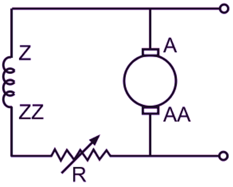
(a)
(b)
Fig. 1: Building up of voltage in a dc shunt generator
If the slope of the field circuit resistance line is reduced by decreasing the field circuit resistance, the maximum voltage that can be built up (decided by the point of intersection of open circuit characteristic and field circuit resistance line) will be higher. Similarly, if the slope of the field circuit resistance line is increased, the final voltage will be lower. If the field circuit resistance is increased to such an extent that field circuit resistance line cuts the open circuit characteristic at point say p’, then the machine will fail to excite at the given speed. If the field circuit resistance is such that the field circuit resistance line becomes tangential to the lower part of open-circuit characteristic, then the machine just excites. This value of the field circuit resistance is called the critical resistance of the shunt field circuit at the given speed. With a series generator, self-excitation and subsequent voltage building is not possible until the load circuit is completed. In the case of a series generator also, the final value of the voltage attained for any speed of operation, is determined by the resistance of the field circuit which now forms the complete load circuit. Further, in this case also, appreciable building of voltage does not take place until the resistance of the entire circuit is reduced to a certain critical value determined by the speed of operation and the magnetization characteristic of the machine. Thus, the following conditions must be satisfied for self-excitation and subsequent voltage building in the case of self-excited dc generators.
- There must be some residual magnetism in the field system. The absence of residual magnetism is indicated by the zero reading of the voltmeter connected across the armature terminals. In such a condition, it may be necessary to connect the field terminals temporarily across a separate power supply such as that from a battery to build the residual magnetism. This is called flashing the field.
- The connection of the field circuit must be proper so that the field current that is established in it strengthens the magnetic field already existing.
- For a shunt generator, the total resistance of the field circuit must be less than the critical resistance corresponding to the given speed.
- For a series generator, the resistance of the complete load circuit must be less than the critical resistance at the given speed.
CRITICAL SPEED OF A SHUNT GENERATOR
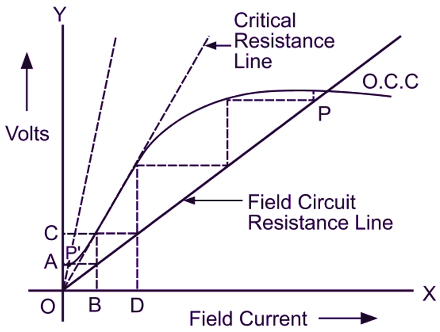
Fig. 2 shows the open circuit characteristic for a shunt generator at its normal speed and its field circuit resistance line. Now as the speed is reduced, the open circuit characteristic proportionally slides downwards (since, E ∝ N when Φ is constant). Hence, the maximum voltage which the machine can build up reduces. At a particular speed, the open circuit characteristic becomes tangential to the field circuit resistance line. As a result the generator just excites at this speed. This speed at which the machine just excites with the given field circuit resistance is known as critical speed of a shunt generator. In other words, the critical speed of a shunt generator is that speed for which the given field circuit resistance itself becomes a critical resistance.

Fig. 2: Critical speed of a shunt generator
In Fig. 2, the dotted curve (O.C.C.) corresponds to critical speed because the field circuit resistance line is tangential to it. If we draw any ordinate ABC cutting critical resistance line for normal speed at A and field resistance line at B, then
\[{{\text{N}}_{\text{C}}}\text{=}\frac{\text{BC}}{\text{AC}}\times \text{N}\]
Hence, Critical speed,
\[\frac{\text{BC}}{\text{AC}}\text{=}\frac{\text{Critical speed}}{\text{Normal speed}}\text{=}\frac{{{\text{N}}_{\text{C}}}}{\text{N}}\]