External Characteristic
The external characteristic of a shunt generator can be obtained by conducting a load test on it in a manner similar to that described for a separately excited generator. The connections are made as shown in Fig. 1 (a). The machine is driven at a normal speed and field current is adjusted to obtain rated no-load voltage. The position of the field rheostat is then kept undisturbed throughout. After this, the load is gradually applied and for different values of load current, corresponding values of terminal voltage are noted. The plot of terminal voltage against load current then gives the external characteristic of a shunt generator (Fig. 1 (b)).
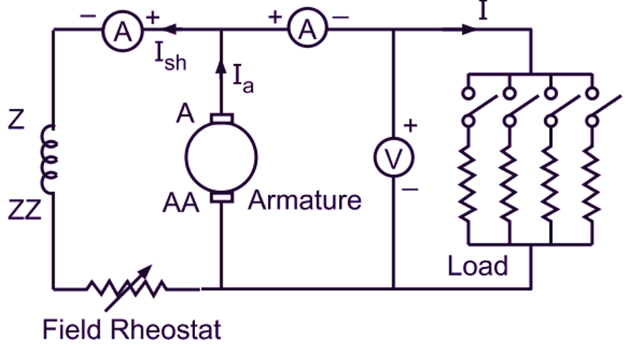
(a)
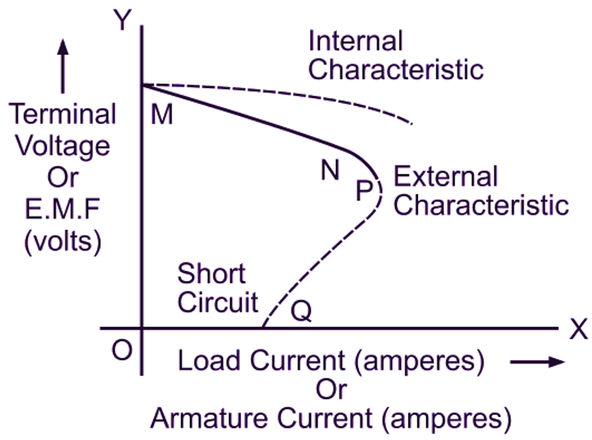
(b)
Fig. 1: (a) Load test on a dc shunt generator, (b) Characteristics of a shunt generator
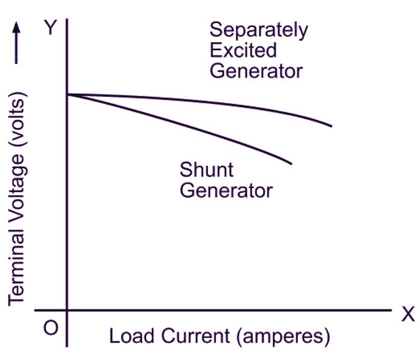
The causes which contribute to the drop in terminal voltage as the load current is increased in the case of a separately excited generator are also present in the case of a shunt generator. However, reduction in the field current due to the decreased terminal voltage on account of the above mentioned factors further drops the terminal voltage of a shunt generator. Hence, the external characteristic of a shunt generator is more drooping in comparison with that of a separately excited generator as illustrated in Fig. 2 (a).
(a)
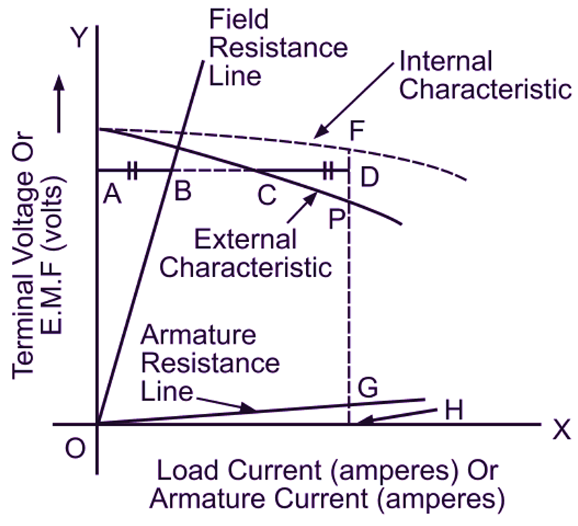
(b)
Fig. 2: (a) Comparison of external characteristics of separately excited and shunt generators, (b) Graphical determination of internal characteristic of a shunt generator from its external characteristic
Now again refer to the external characteristic of a dc shunt generator shown in Fig. 2 (b). The portion MN is the part of the external characteristic over a normal working region of a generator. Over this portion, as the load current is increased by progressive reduction in the load resistance, the terminal voltage falls due to the various reasons mentioned above. Further, this terminal voltage falls rapidly over the portion NP. Beyond point P, the increasing effects of armature reaction, resistance drop and decreasing field current cause the terminal voltage and hence the load current to reduce mole rapidly than the increase in the load current due to decreased load resistance. This ultimately results into decreased load current and therefore the characteristic turns back as shown in the figure. Finally, when the load resistance is reduced to almost zero, the terminals of the generator get short circuited. As a result, the terminal voltage and hence the field current reduces to zero. This condition corresponds to point Q. The short circuit current OQ under this condition is considerably less than the normal full load current and is merely due to the weak residual magnetism (weakened by armature reaction) of the generator. If the shunt generator has to build up its field with the load circuit closed, the load resistance should not be below a certain minimum value called critical resistance for the load. Otherwise, it will fail to excite. Thus the shunt generator has two critical resistances, one for the field circuit and the other for the load.
Internal Characteristic
In the case of a dc shunt generator, we know that
\[{{\text{I}}_{\text{a}}}\text{= I + }{{\text{I}}_{\text{sh}}}\]
and
\[\text{E = V + }{{\text{I}}_{\text{a}}}{{\text{R}}_{\text{a}}}\]
The values of E and la therefore, can be calculated from the data of the load test conducted on the shunt generator and then plotted to obtain the internal characteristic as illustrated in Fig. 1 (b). Very often the field current is so small compared with the load current that it can be neglected.
Graphical Determination of Internal Characteristic
The internal characteristic may also be found graphically from the external characteristic as follows:
As seen earlier, plot the external characteristic from the data of the load test (Fig. 2 (b)). Similarly draw the field resistance line (V/lsh curve) and the armature resistance line (laRa/la curve). After this, select the different points on the external characteristic and find the corresponding points on the internal characteristic one by one. To illustrate the method, consider any point C on the external characteristic. Draw a horizontal line AC through C. For a load current AC at a terminal voltage OA, the shunt field current as given by the field- resistance line is then AB. Extend AC to D such that CD is equal to AB. Then AD is the corresponding armature current (since la = l + lsh). Next, draw the ordinate DGH. Then GH is the armature drop for a current AD. Finally, draw DF equal to GH. Then F is a point on the internal characteristic (since E = V + laRa). Number of points are obtained in a similar manner which when joined give the internal characteristic.