External Characteristic
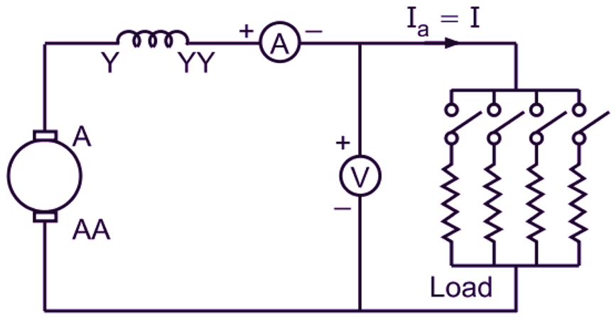
As in the case of a separately excited or shunt generator, for a series generator also, external characteristic is obtained experimentally by conducting a load test. Connections are made as shown in Fig. 1 (a). The generator is driven at normal speed.
(a)
(b)
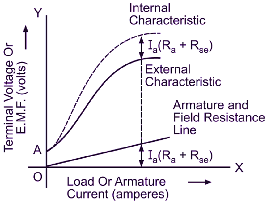
Fig. 1: (a) Load test on a dc series generator, (b) Characteristics of a series generator
The load current is then increased in steps and readings are taken at each step of the value of the load current and of the terminal voltage of the machine. These readings, when plotted, give the external characteristic. Fig. 1 (b) shows the typical external characteristic of a series generator. When the load current (or field current) is zero, the terminal voltage has some small value due to residual magnetism. Hence, the curve starts from A, and not from O. After loading, the load current entirely passes through the field winding. Therefore, as the load current increases, due to increased excitation, the induced emf increases. This ultimately results into increased terminal voltage. Thus, the terminal voltage is directly dependent on the load current and is almost proportional to it until the saturation of the magnetic circuit starts. At high loads, a stage comes when the terminal voltage starts decreasing due to excessive demagnetizing effect of the armature reaction and rapidly increasing armature and field resistance drops.
Internal Characteristic
The values of the induced emf corresponding to different values of the armature currents can be obtained from the data of the load test conducted on a generator using the following relationship:
\[\text{E = V + }{{\text{I}}_{\text{a}}}\left( {{\text{R}}_{\text{a}}}+{{\text{R}}_{\text{se}}} \right)\]
The plot between the induced emf and armature current then gives the internal characteristic (Fig. 1(b)). This characteristic can also be obtained graphically by adding ordinates of the ohmic drop line to the corresponding ordinates of the external characteristic.