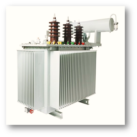
In this topic, you study Distribution Transformer.
These transformers are generally used for stepping down the distribution voltage (3.3 k V, 6.6 kV, 11 kV, 22 kV or 33 kV) to a standard service voltage (400 V). They are kept in operation for all the 24 hours in a day irrespective of whether they are carrying any load or not.
Description of Distribution Transformer given below in tabular form
| Particulars | Distribution Transformers |
| Connections | Delta/Star. Used for three-phase, 4-wire system. |
| Capacity | Commonly used range: 25 kVA to 250 kVA |
| Efficiency | Operated under varying load conditions. Hence, designed to have maximum efficiency at a load much lower than full load. |
| Flux density | Upto 1.7 T (with cold rolled steel). Lower flux density is used so that iron loss is low. |
| Ratio of iron loss to copper loss | 1 : 3
As energy is lost in iron losses throughout the day, these losses are kept small. |
| Voltage regulation | 4 to 6
Designed to have low leakage reactance so as to achieve good voltage regulation. |
| Cooling | Self oil cooled. |
Criteria for the Selection of Three phase Distribution Transformers
The main governing features for the purpose of selection of outdoor type, three phase, double-wound distribution transformers up to and including 1600 kVA are, in brief, as follows :
Ratings: This includes kVA rating, nominal system voltage, no-load voltage ratio and frequency. The kVA rating of the transformers shall be selected from the specified standard ratings as per requirements. The no-load secondary voltage should be 433 V for the transformers to be used in 415 V system. For the transformers to be operated in parallel with other transformers, no-load voltage ratio should be selected in accordance with the necessary requirements.
Taps: The transformers in the range under consideration are normally provided with off-circuit taps on HV side. In special cases, on-load tap changers may be specified. The standard range of off-circuit taps which are provided on HV side should be and . In case of on-load tap changers, the taps may be in steps of 1.25
Connection Symbol: The transformer should be preferably connected in delta/star. The exact connection symbol (Dyn11 or Dy1) is to be specified depending upon requirement of parallel operation with other transformers.
Impedance: Consideration shall be given in the selection of impedance for the standard available rating of the switchgear on the secondary side and associated voltage drops.
Termination Arrangement: The HV and LV terminals may be bare outdoor bushings, cable boxes or bus trunking depending upon the method of installation. Whenever compound filled cable boxes are used, it is preferable to specify disconnecting chamber between transformer terminals and cable box to facilitate the disconnection of the transformer terminals without disturbing the cable connection.
Cooling: The transformers in this group are generally AN, ONAN cooled depending upon transformer kVA ratings and voltage class (in kV).
Fittings and Accessories: These shall mainly include explosion vent, oil temperature indicator, winding temperature indicator, gas actuated relay, breather, etc.
Amorphous Core Type Distribution Transformers
The cores of conventional distribution transformers consist of stacks of laminations that are made from silicon steel with an almost uniform crystalline structure. In amorphous core type distribution transformers, the cores are made from very thin ribbon of ferromagnetic an amorphous metal alloy containing elements such as iron, boron, silicon or phosphorous. This alloy with a non-crystalline structure has excellent mechanical strength and electrical characteristics such as high magnetic susceptibility, low coercivity and high electrical resistance. Random molecular structure of amorphous metal alloy causes less friction than silicon steel when an alternating magnetic field is applied. This unique property which allows ease of magnetization and demagnetization, significantly lowers the hysteresis losses. The high resistance of amorphous metal alloy leads to low eddy current losses when subjected to an alternating magnetic field. Hence, amorphous core type distribution transformers have losses 70-80
Advantages of Amorphous Core Type Distribution Transformers
- No-load losses are 20-30
- Reduced temperature rise of the core.
- Less aging of insulation.
- Better overloading capacity.
- Reduction in fossil fuel consumption.
- Reduced carbon dioxide (CO2) emission, thus reducing the impact on environment. Only important disadvantage that can be mentioned is that the amorphous metal alloy used as a core material requires advanced techniques for machining.