Owen’s Bridge bridge is used for measurement of inductance in terms of a standard capacitance. The Fig. 1 shows the circuit diagram. The bridge has the following components.
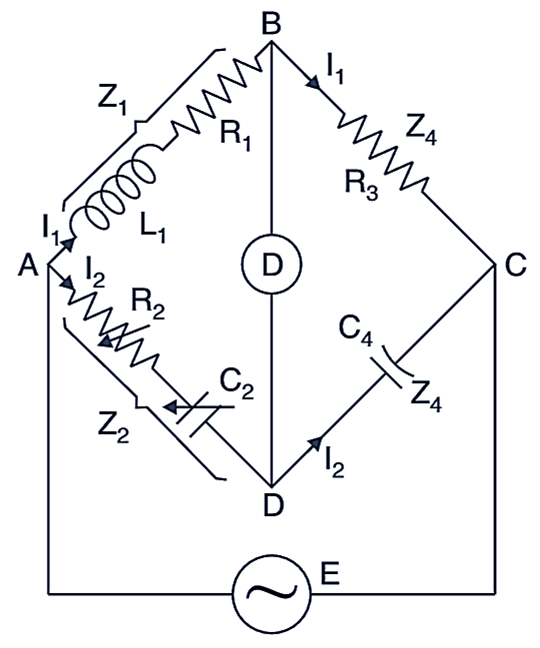
Fig. 1: Owen’s Bridge
L1 = Unknown inductance
R1 = Resistance contained in L1
R2 = Variable non-inductive resistance
R3 = Fixed non-inductive resistance
C2 = Variable capacitor
C4 = Standard capacitor
At balance condition,
\[{{\text{Z}}_{\text{1}}}{{\text{Z}}_{\text{4}}}\text{ = }{{\text{Z}}_{\text{2}}}{{\text{Z}}_{\text{3}}}\]
\[\left( {{\text{R}}_{\text{1}}}\text{+ j}\omega {{\text{L}}_{\text{1}}} \right)\frac{1}{\text{j}\omega {{\text{C}}_{\text{4}}}}\text{ = }\left[ {{\text{R}}_{\text{2}}}\text{+ }\frac{1}{\text{j}\omega {{\text{C}}_{\text{2}}}} \right]{{\text{R}}_{\text{3}}}\]
or
\[\frac{{{\text{R}}_{1}}}{\text{j}\omega {{\text{C}}_{\text{4}}}}\text{+}\frac{{{\text{L}}_{1}}}{{{\text{C}}_{\text{4}}}}\text{ }=~\text{ }{{\text{R}}_{\text{2}}}{{\text{R}}_{\text{3}}}\text{+ }\frac{{{\text{R}}_{\text{3}}}}{\text{j}\omega {{\text{C}}_{\text{2}}}}\]
Now equating real terms
\[\frac{{{\text{L}}_{\text{1}}}}{{{\text{C}}_{\text{4}}}}\text{ = }{{\text{R}}_{\text{2}}}{{\text{R}}_{\text{3}}}\]
or
\[{{\text{L}}_{\text{1}}}\text{ = }{{\text{R}}_{\text{2}}}{{\text{R}}_{\text{3}}}{{\text{C}}_{\text{4}}} ….(i)\]
Equating imaginary terms
\[\frac{{{\text{R}}_{\text{1}}}}{\text{j}\omega {{\text{C}}_{\text{4}}}}\text{ = }\frac{{{\text{R}}_{\text{3}}}}{\text{j}\omega {{\text{C}}_{\text{2}}}}\]
or
\[{{\text{R}}_{\text{1}}}\text{ = }\frac{{{\text{R}}_{\text{3}}}{{\text{C}}_{\text{4}}}}{{{\text{C}}_{\text{2}}}} ….(ii)\]
The value of unknown inductance L1 can be obtained in terms of standard capacitor C4 by eq. (i)
The value of resistance R1 contained in the inductance L1 can also be found out by eq. (ii) in terms of known quantities R3, R4 and C2.
Advantages of Owen’s Bridge
- The balance equations are very simple and are independent of frequency.
- A wide range of inductance can be measured by this bridge.
- The two adjustable elements R2 and C2 are in the same arm. This makes reactive adjustment independent of resistive adjustment and avoids interlocking effect of sliding balance which sometimes causes difficulty when the two adjustments are in the different arms.
Disadvantages of Owen’s Bridge
- The bridge requires a variable capacitor, which is a very expensive component moreover, its accuracy is very less (about 1
- For measuring inductance of coils having high Q factor, the value of C2 required will be very large. It requires a decade capacitor (decade mean 10) which is difficult to obtain