A resistance ‘R’ may be of metal or maybe liquid resistance (used 66 kV or above). Metal resistance is easy for maintenance but being slightly inductive the effect may create breakdown of insulation due to lightning. This drawback is absent in liquid resistance. In case of fault in the line say line B the three currents in it at the fault F are IF, IBR and IBY (Fig. 1 (a)). Fault current IF lags VBN by certain angle (not 90° due to resistance), IBR leads VBR by 90°, so also IBY leads VBY by 90° (Fig. 1 (b)). ICF is the resultant of these two. IF may be resolved into two mutually perpendicular components (reactive and resistive) (as shown by IReac and IRes). The value of resistance R shall be such that it will limit the fault current to the full rating of the largest generator or transformer.
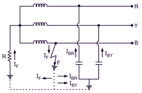
(a) Circuit Diagram
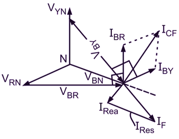
(b) Phasor Diagram
Fig. 1: Resistance Grounding
\[R=\frac{V_{L}}{\sqrt{3}I}\]
where,
R = Resistance
VL = Line volume,
I = Full-load current of largest machine
R may be taken as per the Peterson’s suggestion as,
\[R=(1 to 1.25) \frac{1}{C_{R}+C_{Y}+C_{B}}\]
where, CR, CY, CB are capacitance phase to earth of each phase.
Merits and Demerits of Resistance Grounding
- It permits the use of discriminative protective gear
- Cost of equipment is more than solid type.
- Grounding fault current is less than first method and communication circuits are not affected much.
- Lightning arrestors are necessary
- The equipment has to be selected for higher voltages.
- Extra cost due to providing resistance.
Application of Resistance Grounding
For the system of 33 kV but power capacity is more than 5000 kVA, this system is suitable.
What is Reactance Grounding?
This system is not used. Grounding through impedance is a reactance grounding,
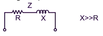
Fig. 1: Reactance Grounding
In this type of grounding, overvoltage or transients may occur due to arcing and higher surge voltage due to lightning and switching. But it is very good for relaying. It reduces interference with communication circuits and cost is intermediate. The circuit arrangement is similar as shown in the next type.