A series inductor filter utilizes the basic property of a inductor by which it opposes any change in the current flowing through it. Whenever the current flowing through an inductor tries to change, a back emf is induced in the inductor and this back emf opposes the current change. A series inductor filter comprises of a large value inductor connected in series with the load resistor as shown in Fig. 1 (a).
Working of Series Inductor Filter
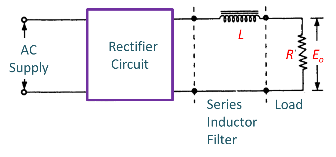
(a) Rectifier circuit with series inductor filter.
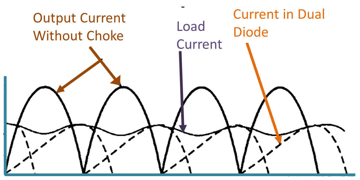
(b) Half wave rectifier output with and without choke.
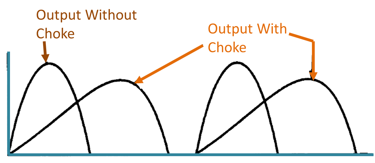
(c) Full-wave rectifier output with and without choke.
Fig. 1: Series Inductor Filter.
Considering Fig. 1 (b) which shows the output of a half wave rectifier with and without an inductor filter, we see that during the positive half cycle when the diode conducts and load current starts increasing to its maximum value, the inductor filter opposes this current rise. In doing so, an energy in the form of magnetic field is stored in the inductor. As a result óf this opposition, the current through load resistor and hence the output voltage Eo is reduced during this period.
When the AC cycle crosses its peak value, the load current tends to reduce but the inductor again opposes this change in the current and tries to maintain load current by giving back the energy stored in it. As a result, the output voltage continues to be present even after the rectifier current has dropped to zero. This can be clearly visualized from waveforms given in Fig. 1 (b) and (c). Thus, the inductor filter increases the DC component across the load with a proportionate decrease in AC components.
Value of Series Inductor Filter
A good inductor filter must offer least resistance to DC component of current and maximum impedance to AC components. But in practice, the inductors offer some resistance to DC also. If the internal resistance of the inductor is Ri then the load voltage will show a reduction as given by the expression
\[\frac{{{E}_{o}}}{E}=\frac{R}{R+{{R}_{i}}}\]
where E is the DC output voltage the rectifier circuit and Eo is the load voltage.
Since, the inductor filter works on the principle of current flowing through it, such a filter works better with a full-wave rectifier as can be seen from Fig. 1 (c). The filtering action depends upon the load current. The larger the load current, the better is the action of the filter and less is the ripple.