The bridge rectifier circuit gives an output similar to that of a full wave rectifier. However, it consists of four diodes arranged in the form of a bridge as shown in Fig. 1. The diodes usually employed are the solid state diodes though vacuum tubes can also be used.
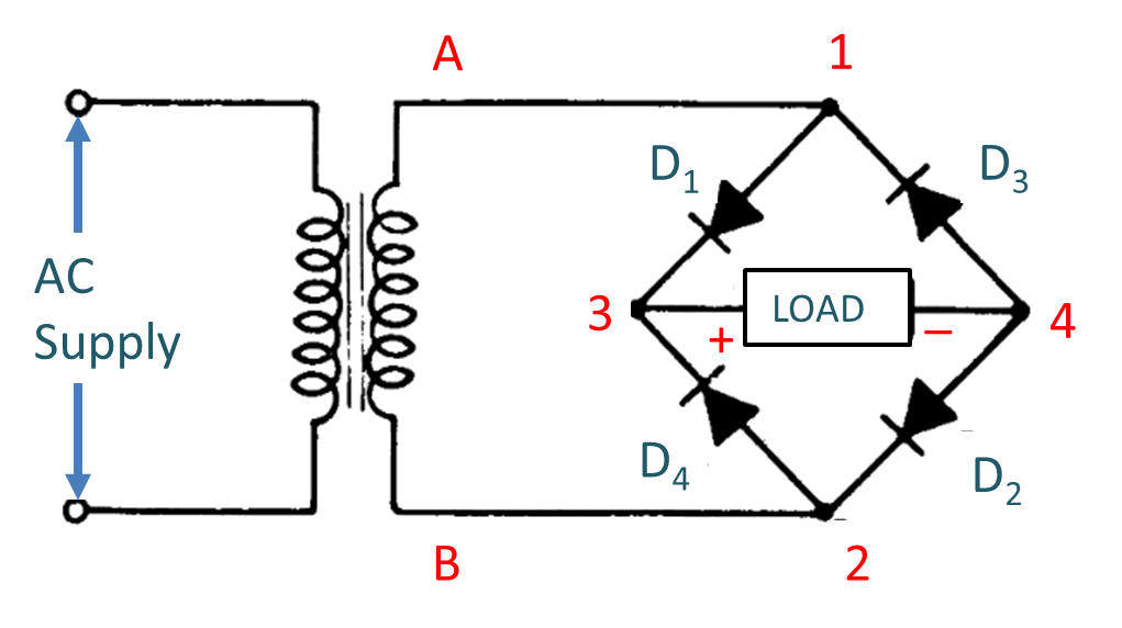
Fig. 1: Circuit arrangement of a bridge rectifier.
Working of Bridge Rectifier
During the positive half cycle of the input supply, the upper end A of the transformer secondary becomes positive with respect to its lower point B. This makes point 1 of the bridge positive with respect to point 2. The diodes D1 and D2 becomes forward biased and D3 and D4 becomes reverse biased. As a result, a current i starts flowing from point 1, through D1 the load and D2 to the negative end, as shown in Fig. 2 where the arrows show the direction of the flow of current. This makes the end 3 of the load positive with respect to end 4.
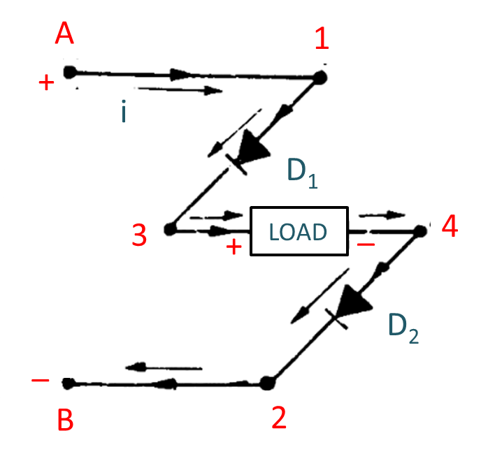
Fig. 2: Current flow during positive half cycles of AC input.
During negative half cycle of the AC input, the point 2 becomes positive with respect to point 1. Diodes D1 and D2 now become reverse biased whereas D3 and D4 are forward biased. Thus a current i flows from point 2 to point 1, through the circuit as shown in Fig. 3. It should, however, be noted that the current through the load is always from point 3 to point 4 whether D1 and D2 conduct or D3 and D4 conduct.
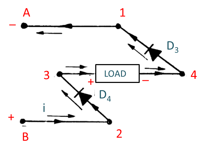
Fig. 3: Current flow during negative half cycles of AC input.
Waveforms of Bridge Rectifier
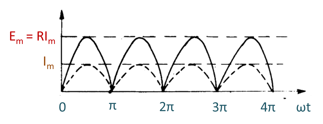
Fig. 4: Wave shape of current and voltage across load resistor.
The wave shape of the current in the load and output voltage are shown in Fig. 4 and are similar to full wave rectifier.
Difference between a full wave rectifier and the bridge rectifier
The main points of difference between a full wave rectifier and the bridge rectifier are given below :
- The inverse voltages across each diode in a bridge rectifier are only half as great as that of a full wave rectifier for the same DC output.
- The transformer secondary winding is fully utilized and centre tape is not required. This reduces the transformer cost in a bridge rectifier.
- Four diodes are used.
- As two diodes are used in series, there is a larger voltage drop across the diodes. This results in poor rectification efficiency.
If step up or step down of the supply voltage is not required, we can use the bridge. Rectifier directly across the main supply, thereby eliminating the need for the transformer. This is not possible with full-wave rectifier. The circuit becomes quite cheaper.