What is De Sauty’s Bridge? Theory, Diagram & Derivation

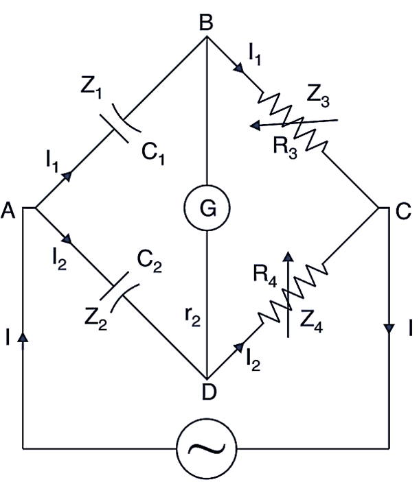
The De Sauty’s bridge is used to measure a capacitance by comparing it with another known/standard capacitance. The circuit has the following components as shown in Fig. 1.
De Sauty Bridge

Fig. 1: De Sauty Bridge.

C1 = unknown capacitor. whose value is to be found out.

C2 = a standard capacitor for comparison

R3, R4 = non-inductive resistors.

The balance is obtained by varying the resistor R3 (or R4).

At balance condition,

\[{{\text{Z}}_{\text{1}}}{{\text{Z}}_{\text{4}}}\text{ = }{{\text{Z}}_{\text{2}}}{{\text{Z}}_{\text{3}}}\]

\[\left( \frac{\text{1}}{\text{j}\omega {{\text{C}}_{\text{1}}}} \right)\cdot {{\text{R}}_{\text{4}}}=\left( \frac{\text{1}}{\text{j}\omega {{\text{C}}_{\text{2}}}} \right)\cdot {{\text{R}}_{\text{3}}}\]

or

\[\frac{{{\text{R}}_{\text{4}}}}{\text{j}\omega {{\text{C}}_{\text{1}}}}=\frac{{{\text{R}}_{\text{3}}}}{\text{j}\omega {{\text{C}}_{\text{2}}}}\]

or

\[\frac{{{\text{R}}_{\text{3}}}}{{{\text{R}}_{\text{4}}}}=\frac{\text{j}\omega {{\text{C}}_{\text{2}}}}{\text{j}\omega {{\text{C}}_{\text{1}}}}\]

or

\[\frac{{{\text{R}}_{\text{3}}}}{{{\text{R}}_{\text{4}}}}=\frac{{{\text{C}}_{\text{2}}}}{{{\text{C}}_{\text{1}}}}\]

or

\[{{\text{C}}_{\text{1}}}={{\text{C}}_{\text{2}}}\cdot \frac{{{\text{R}}_{\text{4}}}}{{{\text{R}}_{\text{3}}}}\]

Now C1 can be calculated as all other quantities are known.

Advantages of De Sauty’s Bridge

  1. It is very simple circuit.
  2. The calculations are also easy.

Disadvantages of De Sauty’s Bridge

  1. If both the capacitors are not free from dielectric loss then it is not possible to obtain the balance condition. This method therefore can be used only for air capacitors, which are more or less loss free.

Problems & Solutions in De Sauty’s Bridge

Problem 1: The null point In a De Sauty bridge is obtained in the following conditions. The arm AB of the bridge contains an unknown capacitor C1, the arm BC contains a resistor R3 = 1,400 Ω, the arm CD contains a R4 = 1,800 Ω and arm DA contains a capacitor C2 of 0.15 μF. Find the unknown capacitor C1.

Solution 1:

\[{{\text{C}}_{\text{1}}}={{\text{C}}_{\text{2}}}\cdot \frac{{{\text{R}}_{\text{4}}}}{{{\text{R}}_{\text{3}}}}\]

\[=\frac{0.15\times {{10}^{-6}}\times 1,800}{1,400}\]

\[=0.192\text{  }\!\!\mu\!\!\text{ F}\]

Thus,

\[{{\text{C}}_{1}}=0.192\text{ }\!\!~\!\!\text{  }\mu \text{ F}\]
What is Q Meter? Working, Diagram, Derivation & Specifications

Every inductor has a certain amount of resistance, which is undesirable as it causes a power loss. The ratio of inductive reactance to the resistance of the coil is called quality factor or Q factor of the coil. i.e.

\[\text{Q}=\frac{{{\text{X}}_{\text{L}}}}{\text{R}}=\frac{\omega \text{L}}{\text{R}}\]

Special meters are designed to measure Q-factor correctly. These are called Q meters. Continue reading What is Q Meter? Working, Diagram, Derivation & Specifications

What is Schering Bridge? Theory, Diagram & Derivation

Schering Bridge is the most popularly used bridge for measurement of unknown capacitance and dielectric loss occurring in the capacitor. The circuit diagram of the Schering bridge is shown in Fig. 1.

Schering Bridge

Fig. 1: Schering Bridge. Continue reading What is Schering Bridge? Theory, Diagram & Derivation

What is Owen’s Bridge? Theory, Diagram, Derivation & Advantages

Owen’s Bridge bridge is used for measurement of inductance in terms of a standard capacitance. The Fig. 1 shows the circuit diagram. The bridge has the following components.

Owen's Bridge

Fig. 1: Owen’s Bridge Continue reading What is Owen’s Bridge? Theory, Diagram, Derivation & Advantages

What is Anderson Bridge? Theory, Diagram, Derivation & Advantages

Anderson bridge is used to measure inductance in terms of a standard capacitance (C). This method is applicable for precise measurement of inductance over a wide range of values, from micro henry to several henries. The Fig. 1. shows the circuit diagram of the bridge. The circuit has the following components. Continue reading What is Anderson Bridge? Theory, Diagram, Derivation & Advantages

What is Trivector Meter? Working & Block Diagram

Trivector meter is an energy meter, which can accurately measure active energy in MWh, Reactive energy in MVArh, apparent energy in MVAh and maximum demand in MVA. These meters are used for commercial and industrial purposes. These electronic meters use microcontrollers (μC) with their own programming language. Continue reading What is Trivector Meter? Working & Block Diagram

What is Maximum Demand Indicator? Working, Diagram & Types

The greatest demand of load during a given period is called maximum demand of the consumer. This is given in kW. Note that the load at a consumer’s premises is not the same all the time. It may be zero at one time and may be maximum at another time. Continue reading What is Maximum Demand Indicator? Working, Diagram & Types