Every inductor has a certain amount of resistance, which is undesirable as it causes a power loss. The ratio of inductive reactance to the resistance of the coil is called quality factor or Q factor of the coil. i.e.
\[\text{Q}=\frac{{{\text{X}}_{\text{L}}}}{\text{R}}=\frac{\omega \text{L}}{\text{R}}\]
Special meters are designed to measure Q-factor correctly. These are called Q meters.
A high value of Q factor is always desirable, as it indicates lower power losses in the coil. Recall that power loss occurs in resistance only (Power loss = (current)2 × resistance) and no power loss occurs in inductance. A typical high quality Q meter can operate from 1 kHz to 300 MHz frequencies.
Principle of Operation of Q meter
The Q meter is an instrument designed to measure Q factor (and some other electrical properties) of coils and capacitors (Fig. 1).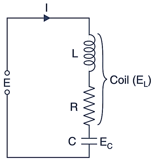
Fig. 1: Q Meter
The operation of this instrument is based on the characteristic of series resonant circuit that the voltage across the coil (or capacitor) is equal to the applied voltage times Q factor. i.e., At resonance
Inductive reactance = Capacitive reactance
i.e.,
\[{{\text{X}}_{\text{L}}}\text{= }{{\text{X}}_{\text{C}}}\]
or
\[\text{I}{{\text{X}}_{\text{L}}}\text{= I}{{\text{X}}_{\text{C}}}\]
or
\[{{\text{E}}_{\text{L}}}\text{= }{{\text{E}}_{\text{C}}}\]
As power loss occurs only in resistance
\[\text{E = IR}\]
From definition
\[\text{Q}=\frac{{{\text{X}}_{\text{L}}}}{\text{R}}=\frac{{{\text{X}}_{\text{C}}}}{\text{R}}=\frac{{{\text{E}}_{\text{C}}}}{\text{R}}=\frac{{{\text{E}}_{\text{L}}}}{\text{R}}\]
where,
E = applied voltage
I = current
EL = voltage across inductor
EC = voltage across capacitor
XL = inductive reactance
XC = capacitive reactance
R = coil resistance
The above discussion reveals that:
- The voltage across L or C is equal to Q times the applied voltage (from above equation. EC = EL = EQ.
- Therefore if E is maintained at constant and known voltage, a voltmeter across the capacitor can be directly calibrated in terms of Q.
Laboratory Type Q-Meter
A practical Q meter is shown in Fig. 1. A wide range oscillator (50 Hz to 50 kHz acts as a supply source: and delivers current to low value shunt resistance Rsh (≈ 0.02 Q). It introduces negligible resistance to the oscillatory circuit and therefore represents a constant voltage source of magnitude E. This voltage (E) obtained across Rsh is measured by a thermocouple meter. The voltage across the variable capacitor C is measured by an electronic voltmeter calibrated directly in terms of Q.
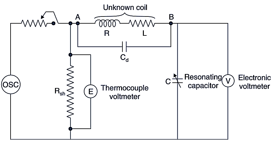
Fig. 2. Q meter
In Fig. 1, Cd is the distributed capacitance of the coil. To measure Q, the unknown coil to be measured is connected between the test terminals (AB) of the instrument and the circuit is tuned to the resonance either by varying frequency of the oscillator or by varying the capacitor C.
The losses in the capacitor and Rsh are included in the reading of the Q meter, therefore the actual (effective) value of Q will be somewhat greater than this reading. This difference may be generally neglected. The value of Q is read by the electronic voltmeter calibrated in tenns of Q.
Specifications of Q Meter
| Q-range | 0 – 50, 0 – 250 |
| Frequency range | 300 kHz – 1000 kHz |
| 1 MHz – 3 MHZ | |
| 3 MHz – 10 MHz | |
| 10 MHz – 20 MHz | |
| Accuracy | 5 |
| Power supply | 230 V, 50 Hz |