Communication by means of sound waves is possible over short distances. If the sound waves are converted into electrical signals, then these signals can be made to travel long distances through transmission lines. Continue reading What is Communication System? Block Diagram & Working
Category: Basic Electronics
What is Amplitude Modulation (AM)? Definition, Derivation, Waveform & Formula
When the peak amplitude of a sinusoidal carrier is changed in proportion to instantaneous amplitude of the modulating signal, amplitude modulated wave is obtained. Fig. 1 shows the principle of amplitude modulation. Continue reading What is Amplitude Modulation (AM)? Definition, Derivation, Waveform & Formula
What is RC Integrator? Circuit Diagram, Working & Waveforms

Figure 1: RC Integrator Circuit.
The RC integrator circuit contains a capacitor C and a resistor R, and their positions are shown in Fig. 1. Here the values of these elements are so arranged that the capacitive reactance offered at the operating signal frequency is very small in comparison to the value of the resistor so that the circuit current is approximately in phase to the input voltage. Continue reading What is RC Integrator? Circuit Diagram, Working & Waveforms
What is RC Differentiator? Circuit Diagram, Working & Waveforms

Figure 1: RC Differentiator Circuit.
A simple RC differentiator circuit consists of a series combination of a capacitor C and a resistor R (see Figure 1). The input signal is fed across the combination and output is obtained across the resistor. Values of C and R are so selected that at the normal operating signal frequencies, the reactance of the capacitor is very large as compared to the resistor. Thus the current flowing in the differentiator circuit is to a large extent decided by the capacitive reactance; the current will be leading the input voltage by 90° approximately. Due to this current, the voltage developed across the resistor also leads the input voltage by 90°. Continue reading What is RC Differentiator? Circuit Diagram, Working & Waveforms
Transistor as a Switch – Circuit Diagram & Working
The transistor when used as a switch must, therefore, be able to operate in cutoff region (open switch) and saturation region (closed switch) only. Continue reading Transistor as a Switch – Circuit Diagram & Working
What is RC Coupled Amplifier? Working, Circuit Diagram & Frequency Response

Fig. 1. RC coupling.
RC Coupling is the simplest and cheapest type of coupling scheme as shown in Fig. 1 and consists of a series coupling capacitor between the amplifier output points and the load circuit. The load may be a simple resistor, a loudspeaker, an antenna in case of a transmitter or another amplifying stage but RC coupling is generally used when a second amplifying stage is used as a load. The series capacitor acts as a short circuit for signal frequencies thereby passing the entire signal to the output, but for DC the capacitor behaves as open circuit. Therefore DC is not passed to the output. Continue reading What is RC Coupled Amplifier? Working, Circuit Diagram & Frequency Response
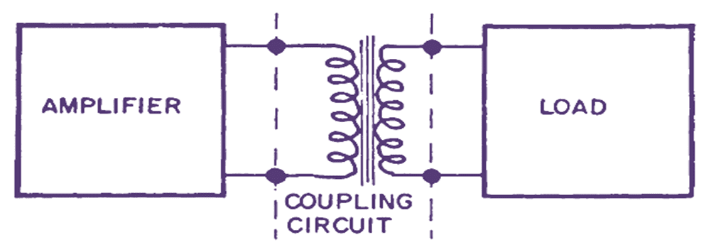
What is Transformer Coupled Amplifier? Working, Circuit Diagram & Applications

Fig. 1. Transformer coupling.
A transformer may also be used for coupling the output of an amplifier to the load as shown in Fig. 1. The transformer ensures that the AC signal is transferred to the load but the DC cannot be passed on to the secondary. The circuit is costlier than RC coupling but has the advantage that the turn ratio of the transformer can be so adjusted as to provide impedance matching and hence maximum energy transfer to the load can be ensured. Continue reading What is Transformer Coupled Amplifier? Working, Circuit Diagram & Applications
What is Bridge Rectifier? Working, Circuit Diagram & Waveforms
The bridge rectifier circuit gives an output similar to that of a full wave rectifier. However, it consists of four diodes arranged in the form of a bridge as shown in Fig. 1. The diodes usually employed are the solid state diodes though vacuum tubes can also be used. Continue reading What is Bridge Rectifier? Working, Circuit Diagram & Waveforms
What is Series Inductor Filter? Working, Diagram, Waveforms & Formula
A series inductor filter utilizes the basic property of a inductor by which it opposes any change in the current flowing through it. Whenever the current flowing through an inductor tries to change, a back emf is induced in the inductor and this back emf opposes the current change. A series inductor filter comprises of a large value inductor connected in series with the load resistor as shown in Fig. 1 (a). Continue reading What is Series Inductor Filter? Working, Diagram, Waveforms & Formula
What is Shunt Capacitor Filter? Working, Diagram & Formula
The Shunt Capacitor Filter comprises of a large value capacitor, which is connected in parallel with the load resistor. Continue reading What is Shunt Capacitor Filter? Working, Diagram & Formula