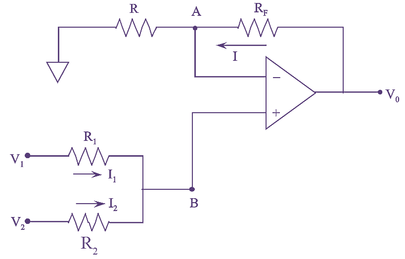
Figure (1): Summing Amplifier.
A summer or an adder circuit which provides non-inverted sum of the input signals is called non-inverting summing amplifier. The circuit diagram of a two input non-inverting type summing amplifier is shown in figure (1).
In figure (1). Assuming that the voltage at node ‘B’ be VB then, the node ‘A’ is at the same potential as that of ‘B’.
\[{{V}_{A}}={{V}_{B}}\]
From the input side,
\[{{I}_{1}}=\frac{{{V}_{1}}-{{V}_{B}}}{{{R}_{1}}}\text{ }\]
And
\[\text{ }{{I}_{2}}=\frac{{{V}_{2}}-{{V}_{B}}}{{{R}_{2}}}\]
But as the input current of op-amp is zero,
\[{{I}_{1}}+{{I}_{2}}=0\]
\[\frac{{{V}_{1}}-{{V}_{2}}}{{{R}_{1}}}+\frac{{{V}_{2}}-{{V}_{B}}}{{{R}_{2}}}=0\]
\[\frac{{{V}_{1}}}{{{R}_{1}}}+\frac{{{V}_{2}}}{{{R}_{2}}}={{V}_{B}}\left[ \frac{1}{{{R}_{1}}}+\frac{1}{{{R}_{2}}} \right]\]
\[{{V}_{B}}=\frac{{{R}_{2}}{{V}_{1}}+{{R}_{1}}{{V}_{2}}}{{{R}_{1}}+{{R}_{2}}}….(1)\]
At node A,
\[I=\frac{{{V}_{A}}}{{{R}_{{}}}}=\frac{{{V}_{B}}}{{{R}_{{}}}}\text{ }\left( {{V}_{B}}={{V}_{A}} \right)….(2)\]
And
\[I=\frac{{{V}_{0}}-{{V}_{A}}}{{{R}_{F}}}=\frac{{{V}_{0}}-{{V}_{B}}}{{{R}_{F}}}….(3)\]
Equating the equation (2) and (3), we get,
\[\frac{{{V}_{B}}}{R}=\frac{{{V}_{0}}-{{V}_{B}}}{{{R}_{F}}}\]
\[\frac{{{V}_{0}}}{{{R}_{F}}}={{V}_{B}}\left[ \frac{1}{{{R}_{{}}}}+\frac{1}{{{R}_{F}}} \right]\]
\[{{V}_{0}}={{V}_{B}}\left[ \frac{R+{{R}_{F}}}{R} \right]….(4)\]
Substituting equation (1) and (4), we get,
\[{{V}_{0}}=\frac{\left( {{R}_{2}}{{V}_{1}}+{{R}_{1}}{{V}_{2}} \right)\left( R+{{R}_{F}} \right)}{R\left( {{R}_{1}}+{{R}_{2}} \right)}\]
\[{{V}_{0}}=\frac{{{R}_{2}}\left( {{R}_{{}}}+{{R}_{F}} \right)}{R\left( {{R}_{1}}+{{R}_{2}} \right)}{{V}_{1}}+\frac{{{R}_{1}}\left( {{R}_{{}}}+{{R}_{F}} \right)}{R\left( {{R}_{1}}+{{R}_{2}} \right)}{{V}_{2}}\]
If \[{{R}_{1}}={{R}_{2}}=R={{R}_{F}},\] we get
\[{{V}_{0}}={{V}_{1}}+{{V}_{2}}\]
As there is no phase difference between the input and output. It is non-inverting summer amplifier.
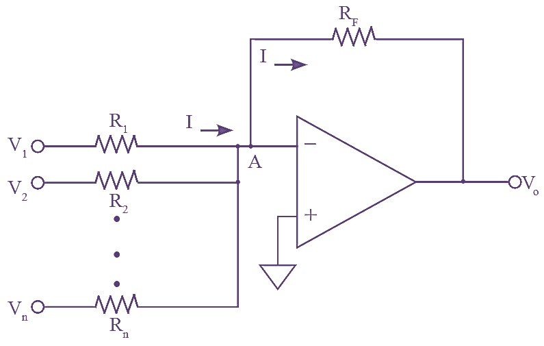
Figure (2): Summing Amplifier with n inputs.
The circuit diagram of summing amplifier with n number of inputs with grounded inverting terminal is as shown in figure (2). It produces an output voltage as a linear addition of all the inputs.
At node A,
\[I=\frac{{{V}_{1}}}{{{R}_{1}}}+\frac{{{V}_{2}}}{{{R}_{2}}}+…….\frac{{{V}_{n}}}{{{R}_{n}}}\]
Since, Vo= – RfI
\[=-\left[ {{V}_{1}}\frac{{{V}_{f}}}{{{R}_{1}}}+{{V}_{2}}\frac{{{V}_{f}}}{{{R}_{2}}}+…..{{V}_{n}}\frac{{{V}_{f}}}{{{R}_{n}}} \right]\]
If R1 = R2=…. Rn = R, then, we get
\[Vo=-\frac{{{R}_{f}}}{R}\left( {{V}_{1}}+{{V}_{2}}+…..+{{V}_{n}} \right)\]